In the following you will find descriptions of functions for graphical and table input, such as CAD tools for designing or generating model and load objects, edit options, operations in spreadsheets, or parameterized input.
4 Model Data
- 4.1 Nodes
- 4.2 Lines
- 4.3 材料
- 4.4 Surfaces
- 4.5 Solids
- 4.6 Openings
- 4.7 Nodal Supports
- 4.8 Line Supports
- 4.9 Surface Supports
- 4.10 Line Hinges
- 4.11 Variable Thicknesses
- 4.12 Orthotropic Surfaces and Membranes
- 4.13 Cross-Sections
- 4.14 Member Hinges
- 4.15 Member Eccentricities
- 4.16 Member Divisions
- 4.17 Members
- 4.18 Ribs
- 4.19 Member Elastic Foundations
- 4.20 Member Nonlinearities
- 4.21 Sets of Members
- 4.22 Intersections
- 4.23 FE Mesh Refinements
- 4.24 Nodal Releases
- 4.25 Line Release Types
- 4.26 Line Releases
- 4.27 Surface Release Types
- 4.28 Surface Releases
- 4.29 Connection of Two Members
- 4.30 Joints
- 4.31 Nodal Constraints
6 Loads
- 6.1 Nodal Loads
- 6.2 Member Loads
- 6.3 Line Loads
- 6.4 Surface Loads
- 6.5 Solid Loads
- 6.6 Free Concentrated Loads
- 6.7 Free Line Loads
- 6.8 Free Rectangular Loads
- 6.9 Free Circular Loads
- 6.10 Free Polygon Loads
- 6.11 Free Variable Loads
- 6.12 Imposed Nodal Deformations
- 6.13 Imposed Line Displacements
- 6.14 Imperfections
- 6.15 Generated Loads
8 Results
- 8.1 Nodes - Support Forces
- 8.2 Nodes - Deformations
- 8.3 Lines - Support Forces
- 8.4 Members - Local Deformations
- 8.5 Members - Global Deformations
- 8.6 Members - Internal Forces
- 8.7 Members - Contact Forces
- 8.8 Members - Strains
- 8.9 Members - Coefficients for Buckling
- 8.10 Member Slendernesses
- 8.11 Sets of Members - Internal Forces
- 8.12 Cross-Sections - Internal Forces
- 8.13 Surfaces - Local Deformations
- 8.14 Surfaces - Global Deformations
- 8.15 Surfaces - Basic Internal Forces
- 8.16 Surfaces - Principal Internal Forces
- 8.17 Surfaces - Design Internal Forces
- 8.18 Surfaces - Basic Stresses
- 8.19 Surfaces - Principal Stresses
- 8.20 Surfaces - Other Stresses
- 8.21 Surfaces - Contact Stresses
- 8.22 Surfaces - Equivalent Stresses - von Mises
- 8.23 Surfaces - Equivalent Stresses - Tresca
- 8.24 Surfaces - Equivalent Stresses - Rankine
- 8.25 Surfaces - Equivalent Stresses - Bach
- 8.26 Surfaces - Basic Strains
- 8.27 Surfaces - Principal Strains
- 8.28 Surfaces - Maximum Strains
- 8.29 Surfaces - Strains - von Mises
- 8.30 Surfaces - Strains - Tresca
- 8.31 Surfaces - Strains - Rankine
- 8.32 Surfaces - Strains - Bach
- 8.33 Solids - Deformations
- 8.34 Solids - Stresses
- 8.35 Solids - Strains
- 8.36 Solids - Gas Pressure
10 Printout
-
10.1 Printout Report
- 10.1.1 Creating or Opening Printout Reports
- 10.1.2 Working in the Printout Report
- 10.1.4 Adjusting Printout Report Headers
- 10.1.5 Inserting RFEM Graphics
- 10.1.6 Inserting Graphics and Texts
- 10.1.7 Printout Report Template
- 10.1.8 Adjusting Layouts
- 10.1.9 Creating Cover Sheets
- 10.1.10 Printing a Printout Report
- 10.1.11 Exporting a Printout Report
- 10.1.12 Language Settings
11 Program Functions
-
11.4 Editing Objects
- 11.4.1 Move and Copy
- 11.4.2 Rotate
- 11.4.3 Mirror
- 11.4.4 Project
- 11.4.5 Scale
- 11.4.6 Shear
- 11.4.7 Dividing Lines and Members
- 11.4.8 Connecting Lines and Members
- 11.4.9 Merging Lines and Members
- 11.4.10 Extending Lines and Members
- 11.4.11 Joining Members
- 11.4.12 Inserting Nodes
- 11.4.13 Inserting Members
- 11.4.14 Assigning Member Properties Graphically
- 11.4.15 Rounding Corners
- 11.4.16 Splitting Surfaces
- 11.4.17 Applying Tangents to Circles
- 11.4.18 Changing the Numbering

持续: 00:00:11 min

持续: 01:19:08 min

持续: 01:06:17 min

持续: 00:02:14 min

持续: 00:00:13 min

持续: 00:00:10 min

持续: 00:00:14 min

持续: 00:00:11 min

持续: 00:00:11 min
.png?mw=350&hash=e7c82f83f96f5d289346b4a2d65b7851c651b4c4)


本文阐述并解释了索的抗弯刚度对其内力的影响。 本文还介绍了如何减少这种影响的方法。
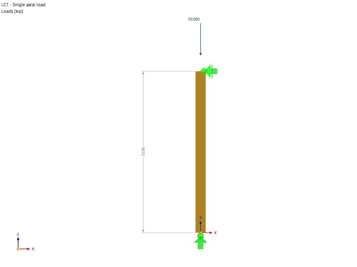
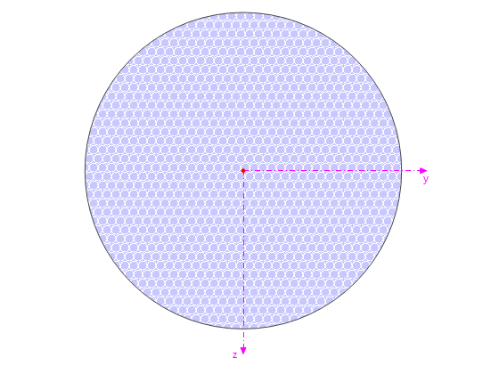
使用“木结构设计”模块,可以按照 2018 NDS 标准 ASD 方法进行木柱设计。 准确计算木杆件的抗压承载力和调整系数对于安全考虑和设计非常重要。 下面的文章将按照 NDS 2018 标准,使用逐步的解析方程验证“木结构设计”模块计算的最大临界屈曲强度,包括受压调整系数、调整后的抗压设计值和最终设计比率。

Die meisten in RFEM und RSTAB vorhandenen Walzprofile können auch mit eigenen Parametern versehen werden. Dazu wird der zu verändernde Querschnitt in der Bibliothek ausgewählt und im Anschluss auf den Button [Parametrische Eingabe...] geklickt.
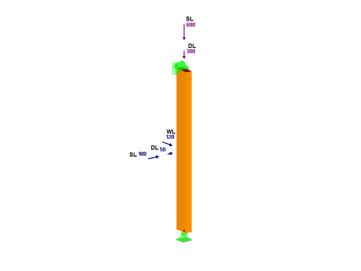
在本文中,使用附加模块 RF-/TIMBER AWC 验证了一个 2x4 尺寸的木材在承受双轴受弯和轴压组合作用的充分性。 梁柱属性和荷载基于 AWC 2015/2018 中木结构设计实例 E1.8 计算得出。


对于验算对象,您可以选择显示垂度或极值结果。
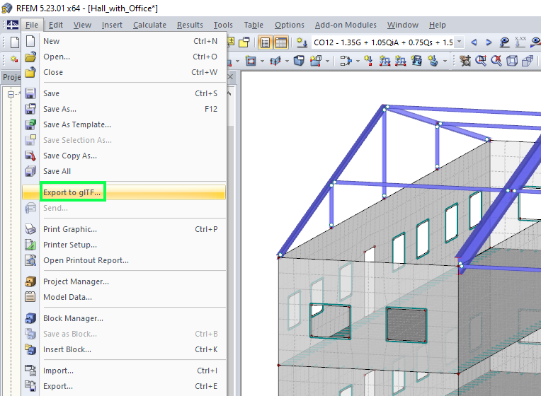
RFEM 和 RSTAB 模型可以另存为 3D glTF 模型(*.glb 和 *.glTF 格式)。 然后在谷歌或 Baylon 的 3D 查看器中详细查看。 戴上虚拟现实眼镜(例如 Oculus)可以“漫步”在结构中。
用户可以按照说明书通过 JavaScript 将 3D glTF 模型集成到自己的网站中(例如在德儒巴网站下载结构分析模型): “在网络和 AR 中轻松显示交互式 3D 模型” .
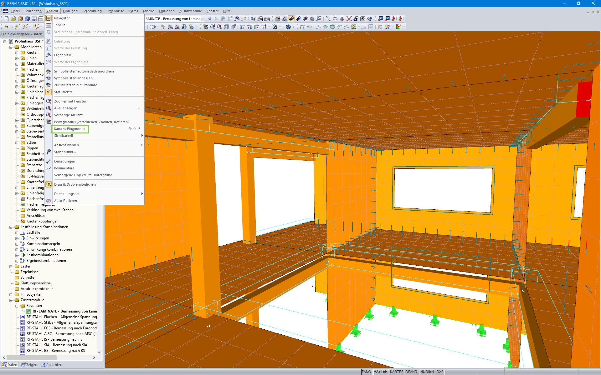
使用视图选项“相机飞行模式”,您可以在 RFEM 和 RSTAB 结构模型中飞行。 使用键盘可以控制飞行的方向和速度。 此外,还可以将在结构模型中的飞行过程保存为视频。
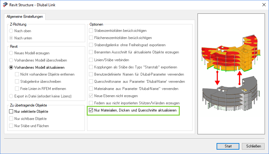
通过与 Revit 的直接接口,您可以根据在 RFEM 或 RSTAB 中所做的更改来更新 Revit 模型。 根据所做的修改,可能必须重新生成 Revit 对象(删除对象然后重新生成)。 重新生成的模型是在 RFEM/RSTAB 的模型基础上进行的
如果你想避免重新生成,请激活'只更新材料、厚度和截面'复选框。 这种情况下只能调整对象的属性。 与此不同的是,材料、面的厚度和截面在这里不予考虑。


