With Dlubal Software, you always have an overview, regardless of whether your projects are from the reinforced concrete, steel, timber, aluminum, or other industry. The program clearly displays the design check formulas used in your design (including a reference to the used equation from the standard). These design check formulas can also be included in the printout report.
Go to Explanatory VideoOutput of Design Check Formulas


Duration: 00:02:15 min

Duration: 00:29:07 min

Duration: 00:45:33 min

Duration: 00:02:38 min

Duration: 01:03:43 min

Duration: 00:02:31 min

Duration: 00:02:19 min

Duration: 00:00:09 min

Duration: 00:00:51 min


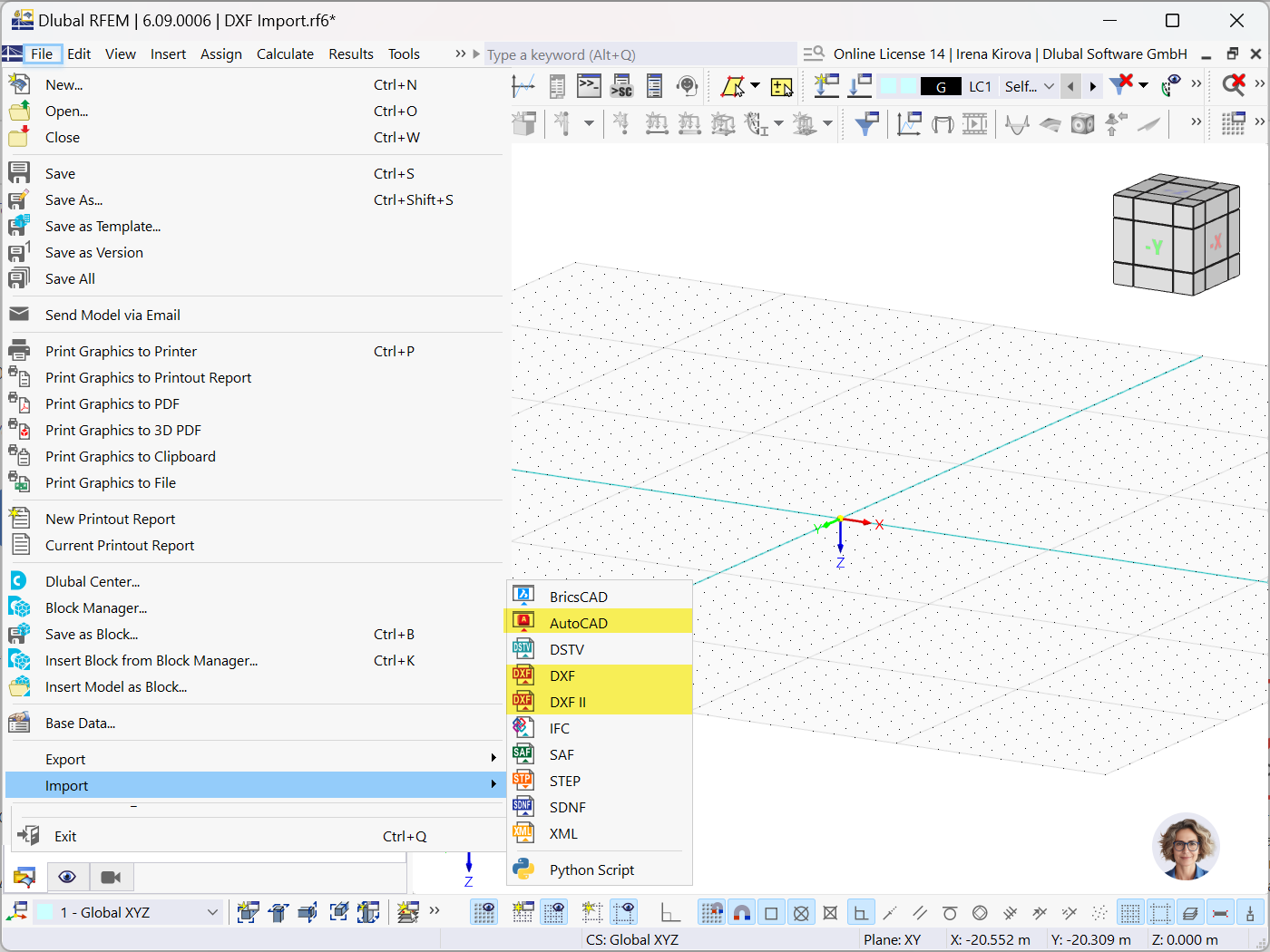
This article outlines the data exchange capabilities between RFEM 6 / RSTAB 9 and AutoCAD, focusing on DXF file integration.

This article explores the importance of considering joint-structure interaction in modeling and design and how to do it in RFEM 6.
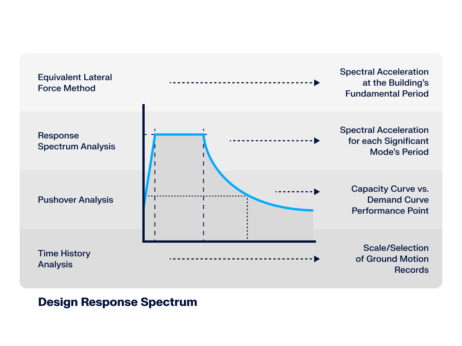
This article* explores the role of the Design Response Spectrum across different seismic analysis methods, demonstrating its significance from simplified static approaches up to advanced dynamic simulations.
.png?mw=512&hash=71474bbf484eff50cf2eb4da2f7c0a5d6103a65d)
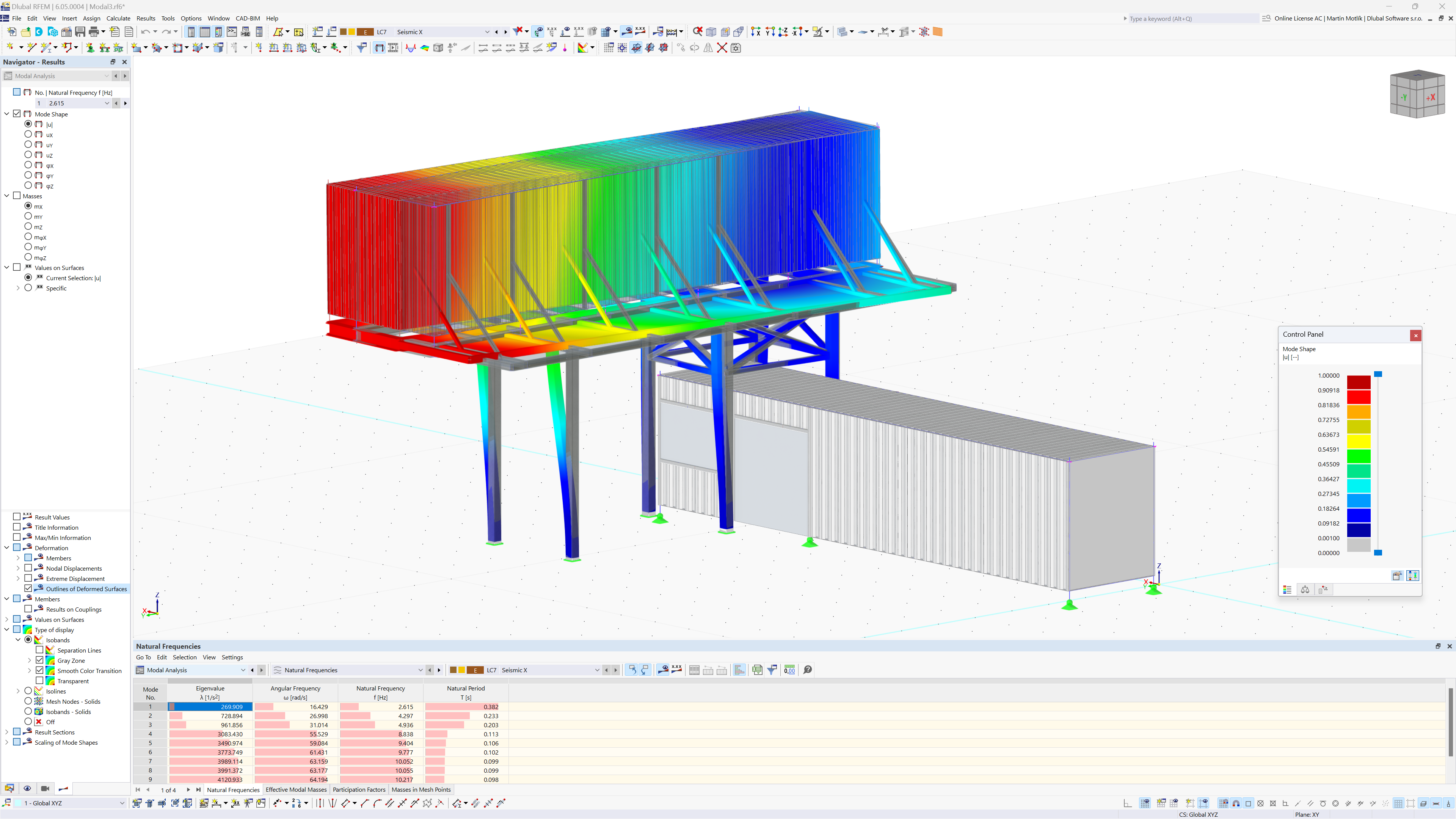
This article provides an overview of RFEM 6 and RSTAB 9's dynamic analysis capabilities, highlighting essential add-ons and learning resources for seismic analysis, vibration-resistant design, and structural dynamics applications.


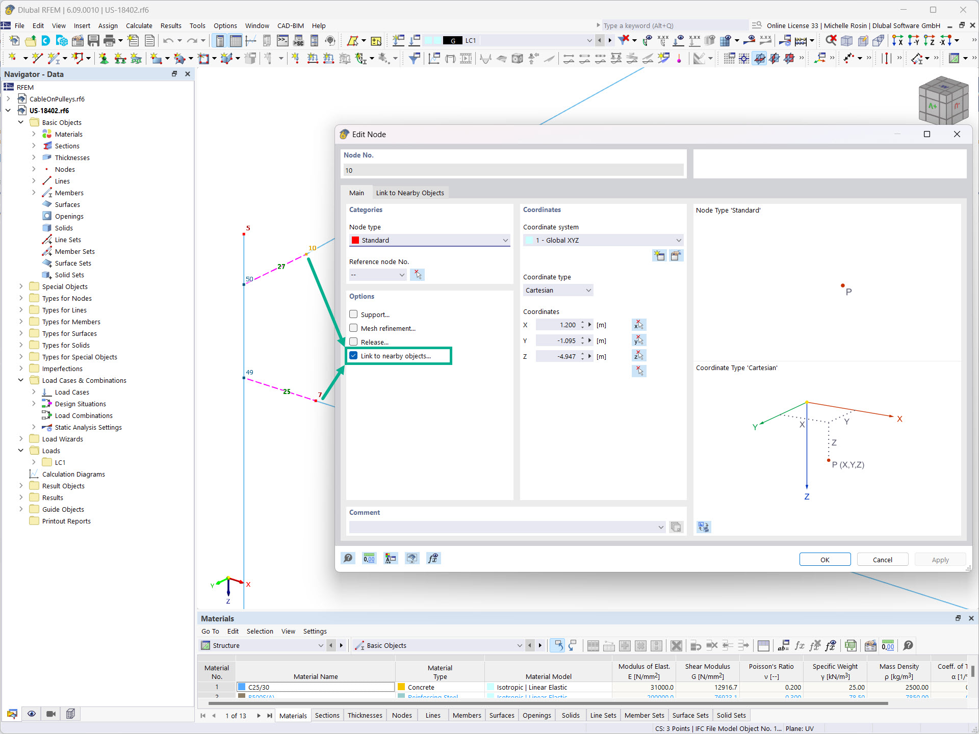
If you activate the "Link to Nearby Objects…" option for nodes, RFEM or RSTAB automatically searches for neighboring objects. A link in the form of a rigid member is then created for these members, nodes, or surfaces.
You can specify various settings for searching for nearby objects. Including search area, object types to be searched for, and objects to be excluded. Furthermore, you can specify member hinges for the created connecting member.
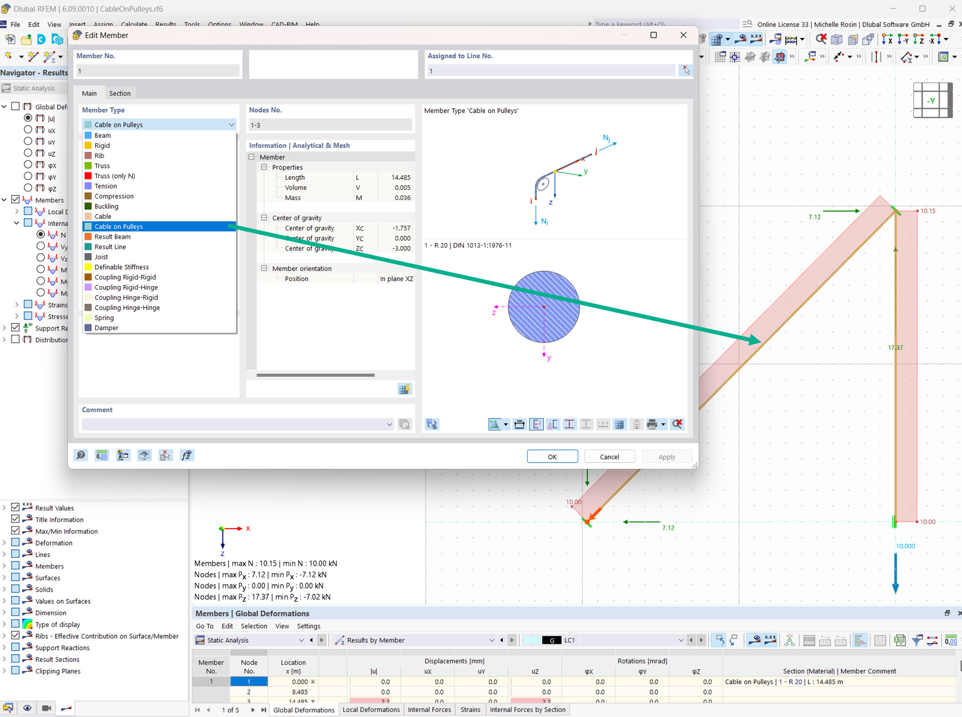
The "Cable on Pulleys" member type allows you to simulate a cable system deflected by pulleys.
This member type only absorbs tensile forces and can only be displaced in the longitudinal direction. It is suitable for flexible tension elements whose longitudinal forces are transferred through the model via deflection points (e.g. pulley).
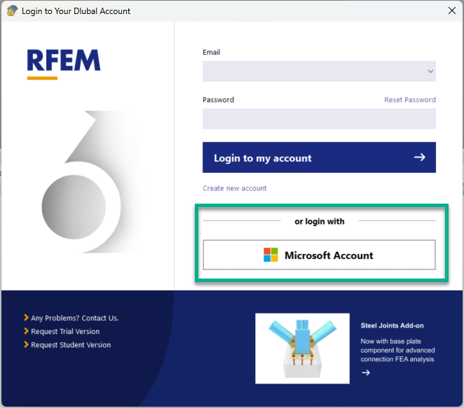
In addition to the program login using your Dlubal account, you can optionally log in with your Microsoft account.
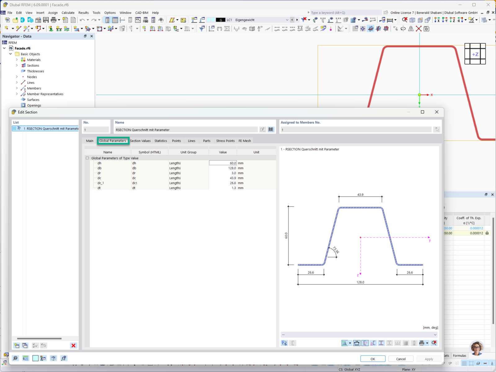
In RFEM and RSTAB, you can use parametric RSECTION cross-sections. If the corresponding parameters have been defined in RSECTION, you can easily modify them in RFEM/RSTAB.
Can I optimize parametric cross-sections?
How can I convert a member set or several members into a single member again?
How does single sign-on work with RFEM 6?
Is it possible to test the API II (gRPC) without incurring costs?
Where can I set the fator for deformation display factor for graphical printout, for example, in the printout report?
Is it possible to consider shear panels and rotational restraints in the global calculation?


-querkraft-hertha-hurnaus.jpg?mw=350&hash=3306957537863c7a7dc17160e2ced5806b35a7fb)


