Control Perimeter
The punching shear check is performed in the basic control perimeter, where a check is made as to whether the acting shear force vEd exceeds the resistance vRd. According to Chapter 6.4.2 of EC 2 [1], the control perimeter for slabs is at a distance of twice the effective depth (d) of the slab from the point of the load application.
The column dimensions as well as the slab openings affect the control perimeter geometry and should be considered up to the distance of 6 d of the load surface. It is important that you define all openings beforehand (that is, during the FEM analysis), so that the program can automatically recognize them and take them into account for the punching design, as shown in Image 1.
Punching Design Parameters in RFEM 6
Assuming that the Concrete Design add-on has already been activated, the punching shear design in RFEM 6 can be initialized by checking the Punching Design box in the design properties of the punching node (Image 2). It is possible to select all nodes where a punching problem has occurred and activate the punching design simultaneously for all of them. Alternatively, the nodes with punching can be selected for design in the Input Data of the Concrete Design table (Image 3).
The punching design parameters for the selected nodes can be defined in the Ultimate Configuration for concrete design (Image 4). Thus, the punching load, the load increment factor β for considering the asymmetrical distribution of shear force in the control perimeter, and the minimum spacing of reinforcement can be set in the Punching tab of the ultimate configuration (Image 5).
The punching load for walls is the shear force (smoothed or unsmoothed) over the critical perimeter, whereas for columns, the punching load can be either the shear force (smoothed or unsmoothed) over the critical perimeter or a single force from column, load, or nodal support.
The load increment factor according to EN 1992-1-1 [1] can be estimated by considering full-plastic shear distribution as shown in Image 6, or by means of constant factors. It can also be determined by a sector model or defined by the user.
Punching Shear Design in RFEM 6
Assuming that the punching design parameters have been defined, the concrete design (including punching) can be performed. First, the design can be done by taking into account only the longitudinal reinforcement, which has already been provided to the surface (Image 7). Once the concrete design is performed considering only this reinforcement, the design ratios in terms of punching shear resistance for all nodes of interest are available both graphically and in the tables (Image 8).
The design ratios on the punching nodes are, in fact, a comparison between the punching shear resistance without shear reinforcement vRd,c determined according to 6.4.4 (1) [1], and the applied maximum shear stress vEd calculated in line with Chapter 6.4.3 (3), Eq. (38). These equations, as well as the whole calculation procedure, can be found in the Design Check Details shown in Image 9.
The punching shear without additional punching reinforcement is fulfilled if vEd ≤ vRd,c; otherwise, additional reinforcement has to be defined. In the latter case, it is possible to define additional longitudinal reinforcement at the tension side of the slab.
For the slab in this example, this will be done by defining additional longitudinal reinforcement at the top side, as shown in Image 10. The defined reinforcement can be assigned to one node, then it can easily be copied to all punching nodes using the common "copy" function (Image 11). The reinforcement assigned in this way will then be considered automatically for the determination of the shear capacity.
Once again, the results are available both graphically and in the Concrete Design table. If the punching shear design without additional punching reinforcement is still not fulfilled, the user can increase the longitudinal reinforcement by applying the maximum allowable longitudinal reinforcement ratio ρ. Nevertheless, if the punching shear design is impossible without punching reinforcement (vRd,c≤ vEd), the maximum punching shear resistance vRd,max is calculated and the design check is performed automatically.
The amount of required reinforcement in terms of punching can be displayed via the Results tab of the navigator (Image 12). If the user is also interested in the punching load used for the calculation, it can be displayed via the Results tab of the navigator as shown in Image 13.
Final Remarks
Punching shear design in RFEM 6 is included in the Concrete Design add-on and it can be initialized by checking the Punching Design box in the Edit Window of the punching nodes. The activation of the design properties will allow the punching design parameters such as the punching load, the load increment factor β, and the minimum spacing of reinforcement to be defined in the Ultimate Configuration for concrete design.
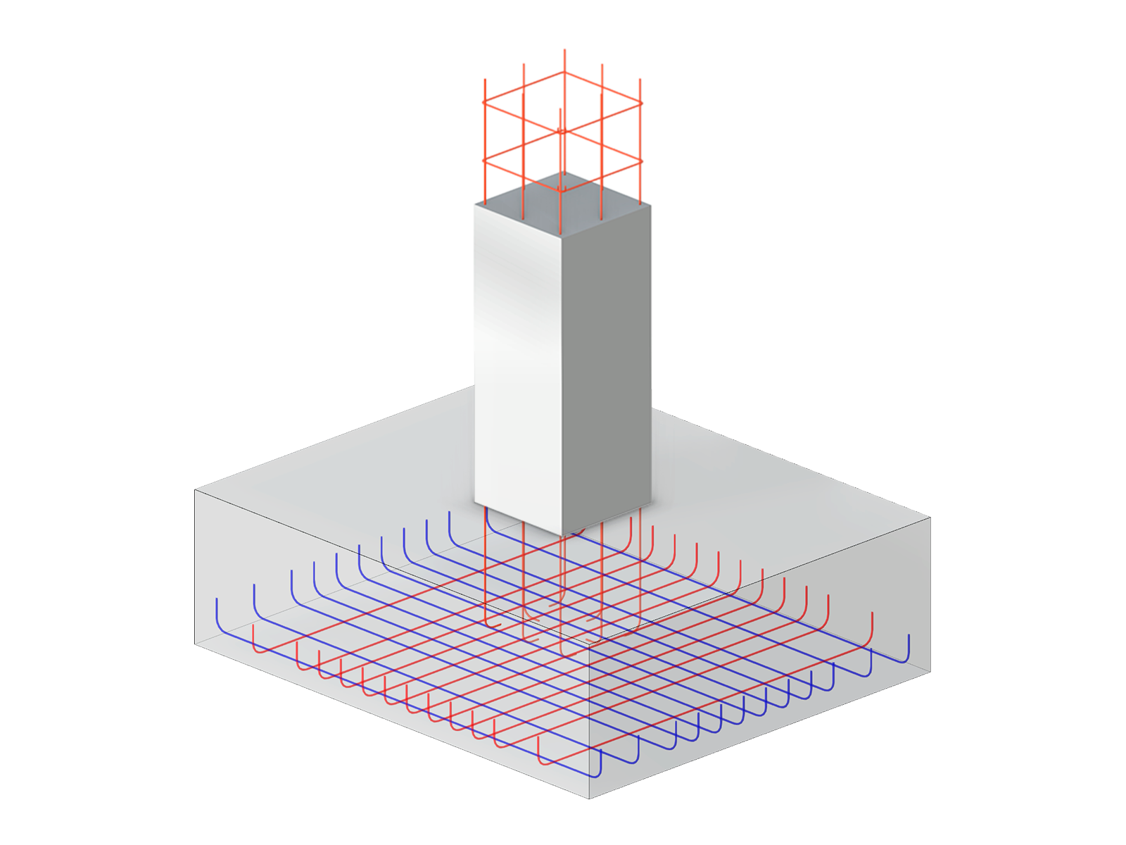
The concrete design can be performed on the basis of the longitudinal reinforcement provided for the other design types. If the punching shear design without additional punching reinforcement is not fulfilled (vRd,c≤ vEd), additional longitudinal reinforcement can be assigned on the tension side of the slab. In this way, the maximum punching shear resistance vRd,max is calculated and the design check is performed automatically.


-querkraft-hertha-hurnaus.jpg?mw=350&hash=3306957537863c7a7dc17160e2ced5806b35a7fb)


.png?mw=600&hash=49b6a289915d28aa461360f7308b092631b1446e)
