The critical load factor is always determined for the entire structure. The corresponding critical loads of the individual members, effective lengths, and effective length factors are calculated on this basis.
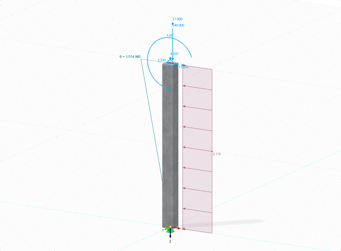
A simple example of a rigid column with load introduction on the head (for example, roof loads) and on the top third (for example, crane loads) exemplifies the procedure in detail.
The critical load factor of 8.591 has been determined for the structural system. This is to be multiplied by the normal forces of members to obtain the critical loads.
Member 1: Ncr,1 = 8.591 × 550 kN = 4,725 kN
Member 2: Ncr,2 = 8.591 × 200 kN = 1,718 kN
The corresponding effective lengths for buckling around both axes are calculated using the adjusted formula Ncr = E × I × π² / Lcr. Finally, the effective load factors are determined from the relation kcr = Lcr / L.
Now, it is possible to perform equivalent member design according to EN 1993‑1‑1. The critical load factors calculated in RF‑STABILITY or RSBUCK can be transferred directly into the RF‑/STEEL EC3 add‑on module. Depending on the model complexity and loading, you should always check whether the stability design using imperfections and internal forces according to the second‑order analysis would be a better alternative.


.png?mw=600&hash=49b6a289915d28aa461360f7308b092631b1446e)
