Polar Moment of Inertia
The connection's polar moment of inertia shown in Figure 01 results in:
|
Ip |
Polares Trägheitsmoment ohne Anteil der Verbindungsmittelflächen |
|
xi |
Abstand vom Schwerpunkt der Verbindungsmittelgruppe zum Verbindungsmittel in x-Richtung |
|
yi |
Abstand vom Schwerpunkt der Verbindungsmittelgruppe zum Verbindungsmittel in y-Richtung |
Ip = 752 + 752 + 2252 +2252 = 112,500 mm2
Modulus of Displacement Determination for the Serviceability Limit State
The modulus of displacement for the serviceability limit state can be calculated according to [1], Table 7.1. For bolts with a diameter of 20 mm in C24 softwood, the modulus per shear plane is calculated as follows:
|
Kser |
Verschiebungsmodul pro Scherfuge |
|
ρm |
Mittelwert der Rohdichte in kg/m³ |
|
d |
Durchmesser des Verbindungsmittel |
Kser = 4201.5 ⋅ 20/23 = 7,485 N/mm = 7,485 kN/m
This results in two shear planes for an internal steel plate. In addition, the modulus of displacement should be multiplied by a factor of 2.0 for steel plate-timber connections according to [1], Chapter 7.1 (3). You can determine the modulus of displacement for the bolt as follows:
Kser= 2 ⋅ 2 ⋅ 7,485 kN/m = 29,940 kN/m
Modulus of Displacement Determination for the Ultimate Limit State
According to [1], the modulus of displacement of a connection in the ultimate limit state, Ku, has to be assumed as follows:
|
Ku |
Anfangsverschiebungsmodul |
|
Kser |
Verschiebungsmodul eines Verbindungsmittels |
Ku = 2/3 ⋅ 29,940 kN/m = 19,960 kN/m
[2] and [3] require considering the design value of the modulus of displacement of a connection.
|
Kd |
Bemessungswert des Verschiebungsmoduls |
|
Ku |
Anfangsverschiebungsmodul |
|
γM |
Teilsicherheitsbeiwert für Verbindungen gemäß [1] Tabelle 2.3 |
Kd = 19,960 kN/m / 1.3 = 15,354 kN/m
Torsional Spring Stiffness Determination
For the ultimate limit state design, you have to use the design value of the slip modulus for calculation and the mean value for the serviceability limit state design; thereby you obtain two torsional spring rigidities.
|
Cφ,SLS |
Drehfedersteifigkeit für den Grenzzustand der Gebrauchstauglichkeit |
|
Kser |
Verschiebungsmodul eines Verbindungsmittels |
|
Ip |
Polares Trägheitsmoment ohne Anteil der Verbindungsmittelflächen |
Cφ,SLS = 29,940 N/mm ⋅ 112,500 mm2 = 3,368 kNm/rad
|
Cφ,ULS |
Drehfedersteifigkeit für den Grenzzustand der Tragfähigkeit |
|
Kd |
Bemessungswert des Verschiebungsmoduls |
|
Ip |
Polares Trägheitsmoment ohne Anteil der Verbindungsmittelflächen |
Cφ,ULS= 15,354 N/mm ⋅ 112,500 mm2= 1,727 kNm/rad
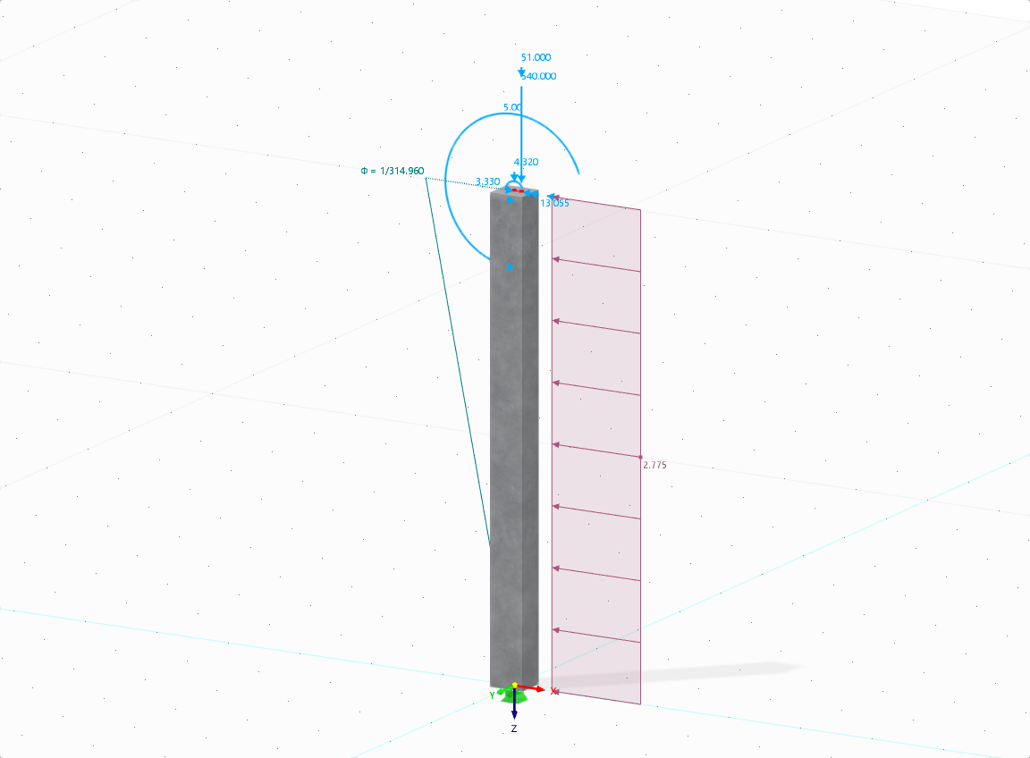
To take both rigidities into account, activate the "Modify Stiffness" sub-tab (select the corresponding check box in the Calculation Parameters sub-tab of the Load Combinations tab in the Edit Load Combinations and Calculations dialog box). As in this example, this allows you to multiply the torsional spring rigidity for all SLS combinations by Cφ,ULS / Cφ,SLS. The value of Cφ,SLS is entered in the support or hinge conditions. Thus, you can calculate with a torsional spring rigidity of 1.727 kNm/rad in all ULS combinations and with 3.368 kNm/rad in all SLS combinations. This approach is also shown in the video.
In this example, the elastic foundation rotation is considered to be infinite and is not taken into account.
Torsional Spring Stiffness Determination Utilizing RF-/JOINTS Timber - Steel to the Timber Add-on Module
When calculating the connection with RF-/JOINTS Timber - Steel to Timber, the results of the torsional spring stiffnesses are also displayed (see Figure 02). In RSTAB, you have to transfer them manually to the support or hinge conditions. In RFEM, this can be done automatically. The connections are automatically created in RFEM and the stiffness is adopted accordingly. The video shows the procedure.



.png?mw=512&hash=4a84cbc5b1eacf1afb4217e8e43c5cb50ed8d827)




_1.jpg?mw=350&hash=ab2086621f4e50c8c8fb8f3c211a22bc246e0552)


-querkraft-hertha-hurnaus.jpg?mw=350&hash=3306957537863c7a7dc17160e2ced5806b35a7fb)


