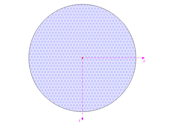
An inner column in the first floor of a three-story building is designed. The column is monolithic connected with the top and bottom beams. The fire design simplified method A for columns according to DIN EN 1992-1-2 is than proofed and the results compared to [1].
| Material | Concrete C35/45 | Design value of concrete compressive strength | fcd | 19.900 | N/mm2 |
| Reinforcing Steel B500S(B) | Design yield strength | fyd | 434.783 | N/mm2 | |
| Geometry | Structure | Column length | lcolumn | 4.200 | m |
| Cross-section | Height | h | 200 | mm | |
| Width | b | 200 | mm | ||
| Cross-section area | Ac | 400 | mm2 | ||
| Loads | Permanant Loads | LC1 | Gk | 363.000 | kN |
| LC2 | Sk | 30.000 | kN | ||
| LC3 | Qk | 150.000 | kN |
RFEM Settings
- The simplified method according to chapter 5 is activated as the method for fire design.
- Permanent and transient for normal temperature acc. to 2.4.2(2) is the design situation type for fire loads.
- The reduction factor fo the design load level ηfi is set to 0,61.
- The flexural buckling ky for the fire design is set to 0.5.
Results
- Inner forces
The governing load combination: 1.35·LC1 + 0.75·LC2 + 1.5·LC3
Normal force NEd [kN] RFEM Analytical solution Ratio 737.550 738.000 1.00
- Effective length and slenderness
'Effective length and slenderness Parameter Description Unit RFEM Analytical solution Ratio ky Effective length factor – 1.000 1.000 1.00 l0 Effective length m 4.200 4.200 1.00 l0 Effective length m 4.200 4.200 1.00 n Relative normal force – 0.930 0.932 1.00 iy Radius of gyration – 57.700 57.700 1.00 λ Slenderness – 72.746 73.000 0.99
- Required reinforcement
Parameter Description Unit RFEM Analytical solution Ratio As,min Minimum longitudinal reinforcement area cm2 2.540 2.540 1.00 As,req required reinforcement cm2 12.480 12.400 1.00
- Fire design
The building where the column is located, is considered as building class 4. The requirement for the column is therefore a fire resistance duration of at least R60. First, the minimum section dimension according to the simplified method A for columns acc. to 5.3.2(1), table 5.2(a):
Minimum section dimension and rebar axis distance acc. to 5.3.2(1) table 5.2a Parameter Description Unit RFEM Analytical solution Ratio ηfi Reduction factor design load level for fire situation – 0.610 0.614 1.00 NEd,fi Axial force in section due to loading for fire design kN 452.856 453.000 1.00 NRd Column capacity kN 798.835 800.000 1.00 μfi Degree of utilization in the fire situation kN 0.570 0.566 1.00 bmin,req Required minimum cross-sectional dimension mm 216.7 217.0 1.00 am,req Required minimum distance mm 39.3 39.3 1.00
Furthermore, the minimum fire duration R is determined. it is calculated as following:
The following equation is used to calculate the fire resistance determined on basis of bearing capacity Rη,fi:
For simplification purposes, the literature assumes that μfi = ηfi. Therefore it is necessary to recalculate Rη,fi using the actual μfi to be able to compare it with the results of RFEM:
| Minimum fire duration acc. to Eq. 5.7 | |||||
| Parameter | Description | Unit | RFEM | Analytical solution | Ratio |
| μfi | Degree of utilization in the fire situation | kN | 0.570 | 0.570 | 1.00 |
| ω | Mechanical reinforcement ratio | – | 0.689 | 0.690 | 1.00 |
| Rη,fi | Fire resistance determined on basis of bearing capacity | – | 35.948 | 35.690 | 1.00 |
| Ra | Fire resistance determined on basis of reinforcement cover | – | 16.000 | 16.000 | 1.00 |
| Ri | Fire resistance determined on basis of buckling length | – | 27.840 | 27.800 | 1.00 |
| Rb | Fire resistance determined on basis of cross-sectional dimension | – | 18.000 | 18.000 | 1.00 |
| Rn | Fire resistance determined on basis of number of bars | – | 0 | 0 | 1.00 |
| R | Time of fire resistance | min | 83 | 82 | 1.01 |


.png?mw=350&hash=c6c25b135ffd26af9cd48d77813d2ba5853f936c)


,_LC1__LI.jpg?mw=350&hash=35da17f7b39d287e41788cfc854d3e0126035f4d)


_1.jpg?mw=350&hash=ab2086621f4e50c8c8fb8f3c211a22bc246e0552)


-querkraft-hertha-hurnaus.jpg?mw=350&hash=3306957537863c7a7dc17160e2ced5806b35a7fb)


.png?mw=600&hash=49b6a289915d28aa461360f7308b092631b1446e)


