When evaluating the results of a line, the program always displays all surface results adjacent to this line; it is easy to lose track. Therefore, it is better to use "Sections". The advantage of this is that you can select only the surfaces with the results you want to evaluate. Moreover, you can display a graphical resultant of these sections. This way, you can quickly review in which area the forces act.
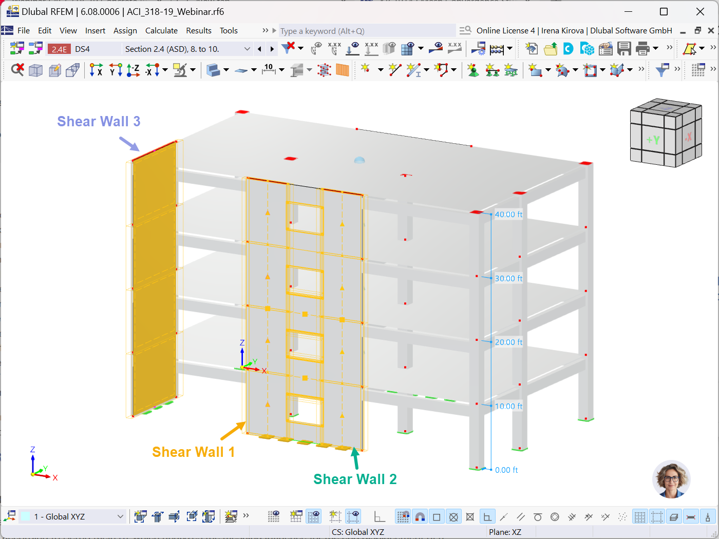
In this example, force of 5 kN/m × 8 m = 40 kN is introduced into a roof slab, and additional force of 8 kN/m × 8 m = 64 kN into a ceiling slab (total = 40 + 64 = 104 kN). They have to be introduced into the walls by means of shear.
Roof slab check: (19.46 + 0.17 + 19.94 + 0.40) kN = 40 kN
Ceiling slab check: (51.23 + 0.31 + 51.55 + 0.88) kN = 104 kN
The accuracy depends on the size of the FE elements. In order to obtain clear a view of the resultants, it is necessary to define separate surfaces. In other words: The walls should not continue through the ceiling slabs.
The relation of the resultants is explained in this article:



.png?mw=512&hash=4a84cbc5b1eacf1afb4217e8e43c5cb50ed8d827)




_1.jpg?mw=350&hash=ab2086621f4e50c8c8fb8f3c211a22bc246e0552)


-querkraft-hertha-hurnaus.jpg?mw=350&hash=3306957537863c7a7dc17160e2ced5806b35a7fb)


