Question
What is the meaning of the superposition according to the SRSS rule in a dynamic analysis?
Answer:
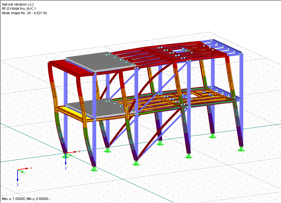
Under Settings, you can define how to combine the results from different mode shapes of a structure. The modal combination is the first step of dynamic combinations. The modal responses can be combined with the Square Root of the Sum of Squares (SRSS) or the Complete Quadratic Combination (CQC). Both of these quadratic combinations can be applied in the standard form or modified as an equivalent linear combination. The standard form of the SRSS rule combines the maximum results and the algebraic signs are lost; the combination expression is as follows:
${\mathrm E}_{\mathrm{SRSS}}\;=\;\sqrt{\mathrm E2\;1\;+\;\mathrm E2\;2\;+\;\dots\;+\;\mathrm E\;2}$
In the RF‑DYNAM Pro add-on module for RFEM, a modified form of the SRSS rule is available to determine the corresponding results, such as the corresponding internal forces. In comparison with the standard form of the SRSS rule, the corresponding internal forces are significantly smaller. Furthermore, the corresponding signs are correct in relation to the governing internal force. The SRSS rule is used as an equivalent linear combination:
${\mathrm E}_{\mathrm{SRSS}}\;=\overset{\mathrm p}{\underset{\mathrm i=1}{\sum{\mathrm f}_{\mathrm i}}}{\mathrm E}_{\mathrm i}$
where:
$f_i=\frac{E_i}{\sqrt{{\displaystyle\sum_{i=1}^p}E_j^2}}$
If applying this formula, the results are consistent.
Do you have any questions?
![Determination of Maximum Horizontal and Vertical Loads to Calculate Stability Coefficient](/en/webimage/009097/2416928/01-en-png.png?mw=512&hash=e5b08a40fd9a5a16825be6182b3138f78627561e)
RFEM offers the option to perform a response spectrum analysis according to ASCE 7-16. This standard describes the determination of seismic loads for the American market. It might happen that the P-Delta effect has to be considered due to the stiffness of the entire structure in order to calculate the internal forces and carry out the design.
![KB 001883 | Plate Girder Design According to AISC 360-22 in RFEM 6](/en/webimage/051561/3980997/im1.png?mw=512&hash=b8237709c4f30213fac51d86d32a42bddde72f03)
Plate girder is an economical choice for long spans construction. I-section steel plate girder typically has a deep web to maximize its shear capacity and flange separation, yet thin web to minimize the self-weight. Due to its large height-to-thickness (h/tw) ratio, transverse stiffeners may be required to stiffen the slender web.
![Steel Connection Rigidity and Its Influence on Structural Design](/en/webimage/051432/3972404/Rigidity-caseA.png?mw=512&hash=3be64e68ab2956fd2b92f0afa1559b3a8c72b468)
Understanding steel connection rigidity is crucial in structural design. Often, connections are treated as strictly pinned or rigid, but this can lead to uneconomical or even dangerous designs. Explore how Dlubal Software's RFEM and Steel Joints add-on help verify connection stiffness and moment resistance, ensuring safer and more economical designs.
![Timber Panel Wall Stiffnesses](/en/webimage/049956/3893282/49956.png?mw=512&hash=8dfc2b6d0af6ade74073e21655c6a73a34a77751)
In this article, the calculation of a timber panel wall with the beam panel thickness type is compared with a manual calculation.
![Add-on "Steel Joints for RFEM 6" | Component Library](/en/webimage/043097/3898884/steel_joints_components.png?mw=512&hash=e4f835906155863fc7019d5043b22e553dc766f9)
- Numerous component types, such as base and end plates, web angles, fin plates, gusset plates, stiffeners, tapers, or ribs for easy input of typical connection situations
- Universally applicable basic components (such as plates, welds, bolts, auxiliary planes) for modeling complex connection situations
- Graphical display of the connection geometry with dynamic updating during the input
- Wide range of cross-section shapes: I-sections, U-sections, angles, T-sections, hollow sections, built-up cross-sections and thin-walled sections
- Library in the Dlubal Center with a large number of program-side template connections, including user-defined templates
- Automatic adaptation of the connection geometry based on the relative arrangement of the components to each other – even in case of subsequent editing of the structural components
![Feature 002828 | Fire Design of Slabs and Walls According to Simplified Table Method](/en/webimage/050837/3925042/50837.png?mw=512&hash=b06639a36ab8b62ab6d08e08552a5ec274469a37)
In the Concrete Design add-on for RFEM 6, you can perform the fire design of reinforced concrete slabs and walls according to the simplified table method (EN 1992‑1‑2, Section 5.4.2 and Tables 5.8 and 5.9).
![Feature 002826 | Punching Shear Reinforcement](/en/webimage/050658/3936123/50658.png?mw=512&hash=ae20d4ca78cdf203a2c2d3ccbb7daa0f324da77a)
In the Concrete Design add-on, you have the option to define an existing vertically oriented punching shear reinforcement. This is then taken into account in the punching shear design.
![Feature 002824 | OSB Material for USA and Canada](/en/webimage/050460/3955503/2024-06-28_10-42-39.png?mw=512&hash=5ec86ff7955d8c9a50e53301df3f21fceda009a5)
In RFEM, the oriented strand board (OSB) material is available for the USA and Canada. The material parameters are taken from the "Panel Design Specification manual".
Recommended Products for You