

Structural model made of steel. The structure consists of a grid-like framework composed of triangular elements, creating a mesh that forms the surface of the dome. The model is a three-dimensional truss structure with a semi-spherical form and an opening on one side, demonstrating advanced architectural design and engineering principles. The overall form is characterized by its curved surface and the uniformity of the triangular grid, which provides both aesthetic appeal and structural stability.
Overall
This page has 0 user ratings.
| 5 star | ||
| 4 star | ||
| 3 star | ||
| 2 star | ||
| 1 star |
Steel Round Grind Shell
| Number of Nodes | 169 |
| Number of Lines | 456 |
| Number of Members | 456 |
| Number of Surfaces | 0 |
| Number of Solids | 0 |
| Number of Load Cases | 1 |
| Number of Load Combinations | 4 |
| Number of Result Combinations | 0 |
| Total Weight | 6.526 tons |
| Dimensions (Metric) | 14.000 x 7.000 x 14.000 m |
| Dimensions (Imperial) | 45.93 x 22.97 x 45.93 feet |
You can download this structural model to use it for training purposes or for your projects. However, we do not assume any guarantee or liability for the accuracy or completeness of the model.


Duration: 00:01:01 min

Duration: 00:49:22 min
.png?mw=350&hash=c6c25b135ffd26af9cd48d77813d2ba5853f936c)
Duration: 00:02:51 min

Duration: 00:00:46 min

Duration: 00:00:56 min

Duration: 00:53:57 min

Duration: 01:05:10 min

Duration: 01:24:40 min

Duration: 00:00:40 min


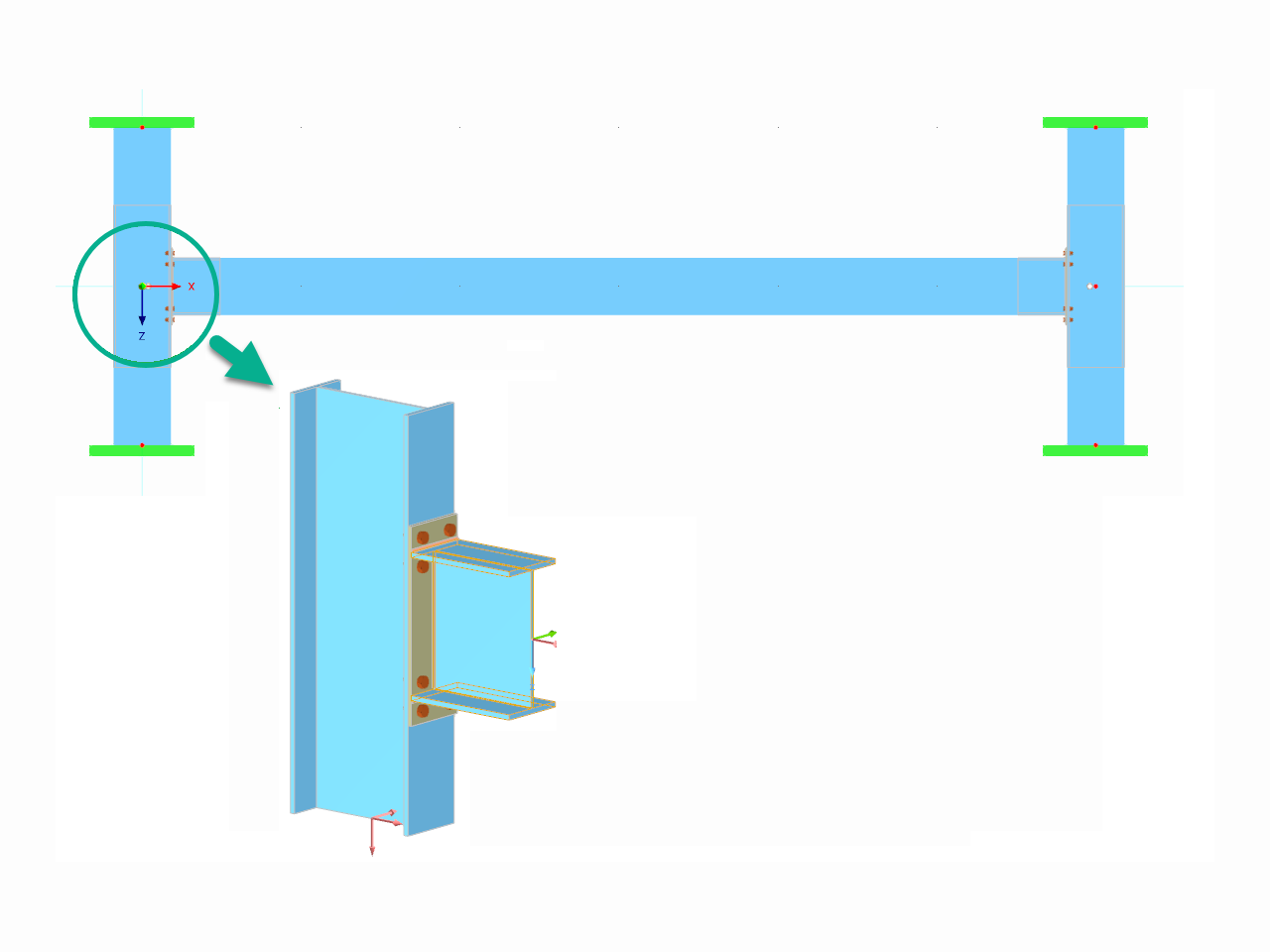
This article explores the importance of considering joint-structure interaction in modeling and design and how to do it in RFEM 6.
.png?mw=512&hash=4a84cbc5b1eacf1afb4217e8e43c5cb50ed8d827)
This article provides a comprehensive overview of essential seismic analysis methods, explaining their principles and applications, as well as the scenarios in which they are most effective

The weld stresses between surfaces can be determined using the Stress-Strain Analysis add-on in RFEM 6. Furthermore, the stress limit determined according to the applicable standard can be input to determine the stress ratio of the weld. This article focuses on the fillet weld design according to AISC 360-22 [1] with two examples from AISC Volume 1: Design Examples [2].
This article demonstrates how to initiate and conduct the analysis in the software, followed by a short discussion of the underlying concept.


In the "Edit Section" dialog box, you can display the buckling shapes of the Finite Strip Method (FSM) as a 3D graphic.

- Design of five types of seismic force-resisting systems (SFRS) includes Special Moment Frame (SMF), Intermediate Moment Frame (IMF), Ordinary Moment Frame (OMF), Ordinary Concentrically Braced Frame (OCBF), and Special Concentrically Braced Frame (SCBF)
- Ductility check of the width-to thickness ratios for webs and flanges
- Calculation of the required strength and stiffness for stability bracing of beams
- Calculation of the maximum spacing for stability bracing of beams
- Calculation of the required strength at hinge locations for stability bracing of beams
- Calculation of the column required strength with the option to neglect all bending moments, shear, and torsion for overstrength limit state
- Design check of column and brace slenderness ratios

The seismic design result is categorized into two sections: member requirements and connection requirements.
The "Seismic Requirements" include the Required Flexural Strength and the Required Shear Strength of the beam-to-column connection for moment frames. They are listed in the ‘Moment Frame Connection by Member’ tab. For braced frames, the Required Connection Tensile Strength and the Required Connection Compressive Strength of the brace are listed in the ‘Brace Connection by Member’ tab.
The program provides the performed design checks in tables. The design check details clearly display the formulas and references to the standard.

In the Steel Design add-on, you can perform the stability and cross-section design checks of cold-formed sections according to EN 1993‑1‑3 in compliance with Sections 6.1.2 – 6.1.5 and 6.1.8 – 6.1.10.
Go to Explanatory VideoIn the Steel Joints add-on, I get high utilization ratios for preloaded bolts in the tension design. Where do these high utilization ratios come from and how can I evaluate the load-bearing reserves of the bolt?
How can treating a connection as fully rigid result in an uneconomical design?
Is it possible to consider shear panels and rotational restraints in the global calculation?
A steel joint in my model is non-designable. How can I get more information to find the cause?
I am calculating a support that is clamped at the base, held in the X direction at the head, and can buckle in the Y direction. I have set the bar shear lengths using node carriers. In the verification, the buckling length values for the calculation are the same, L_(cr,z) = L_(cr,y) = 2.41 m. What am I doing wrong?
What is the Function of Chained Analysis Diagram?


-querkraft-hertha-hurnaus.jpg?mw=350&hash=3306957537863c7a7dc17160e2ced5806b35a7fb)


