

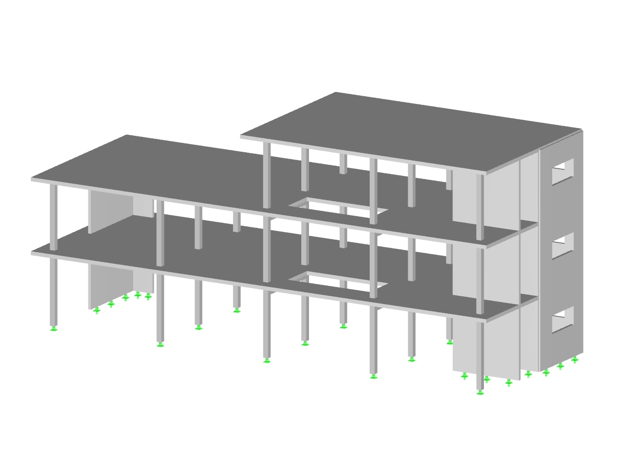
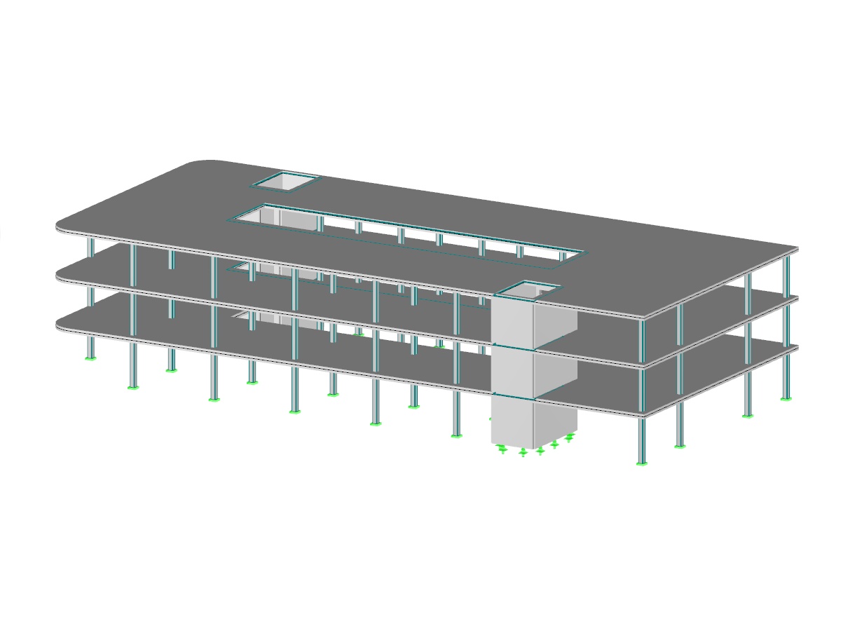
Concrete member and surface structure modeled in RFEM. The webinar in the link below demonstrates the design workflow according to the ACI 318-14 standard utilizing the RF-CONCRETE Members and Surfaces add-on modules.
Model Used in
Overall
This page has 0 user ratings.
| 5 star | ||
| 4 star | ||
| 3 star | ||
| 2 star | ||
| 1 star |
ACI 318-14 Concrete Structure
| Number of Nodes | 101 |
| Number of Lines | 141 |
| Number of Members | 8 |
| Number of Surfaces | 16 |
| Number of Load Cases | 5 |
| Number of Load Combinations | 31 |
| Number of Result Combinations | 2 |
| Total Weight | 219.224 tons |
| Dimensions (Metric) | 14.585 x 11.585 x 6.181 m |
| Dimensions (Imperial) | 47.85 x 38.01 x 20.28 feet |
| Program Version | 5.23.00 |
You can download this structural model to use it for training purposes or for your projects. However, we do not assume any guarantee or liability for the accuracy or completeness of the model.
Related Models
.png)


Duration: 00:00:45 min

Duration: 00:00:55 min

Duration: 00:00:00 min

Duration: 00:00:46 min

Duration: 00:00:31 min

Duration: 00:00:38 min

Duration: 00:00:50 min


Duration: 00:01:31 min


.png?mw=350&hash=89d38ebf39f87b491d2323def2362f69bd26ca8d)


For the design of concrete surfaces, the rib component of the internal forces can be neglected for the ULS calculation and for the analytical method of the SLS calculation, because this component is already considered in the member design. To do this, select the check box in the "Details" dialog box. If no rib was defined, this function is not available.

Shrinkage and creep are time-dependent deformation properties of concrete that usually have to be considered in the serviceability limit state design.

For reinforced concrete components and structures with structural behavior considerably influenced by the effects of the second-order analysis, Eurocode 2 provides the general method based on a nonlinear determination of internal forces according to the second-order analysis (5.8.6), as well as the approximation method based on the nominal curvature (5.8.8).
The aim of this technical article is to perform a design according to the general design method of Eurocode 2, using the example of a slender reinforced concrete column.
The aim of this technical article is to perform a design according to the general design method of Eurocode 2, using the example of a slender reinforced concrete column.
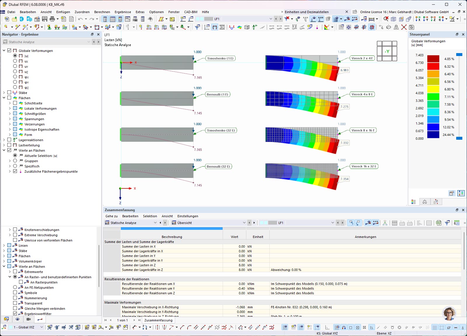
In simulations using the finite element method, the mesh is of crucial importance. This article describes the essential features of a mesh convergence study to determine the required mesh refinement for sufficiently accurate results.


![Result Window 2.1 in RF-CONCRETE Surfaces with Calculated Reinforcement Surfaces in [cm²/m]](/en/webimage/018953/2268354/01-de.png?mw=350&hash=ef629ee1c00df85a43bf1b3ef20a5415a41393a1)


The deformation process of the global deformation components can be represented as a movement sequence.

Result values for deformations, internal forces, stresses, and so on, can be displayed on the isolines.
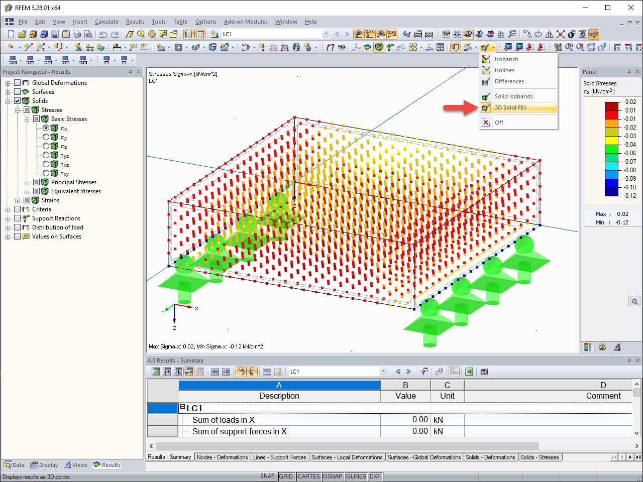
The results of solid stresses can be displayed as colored 3D points in the finite elements.
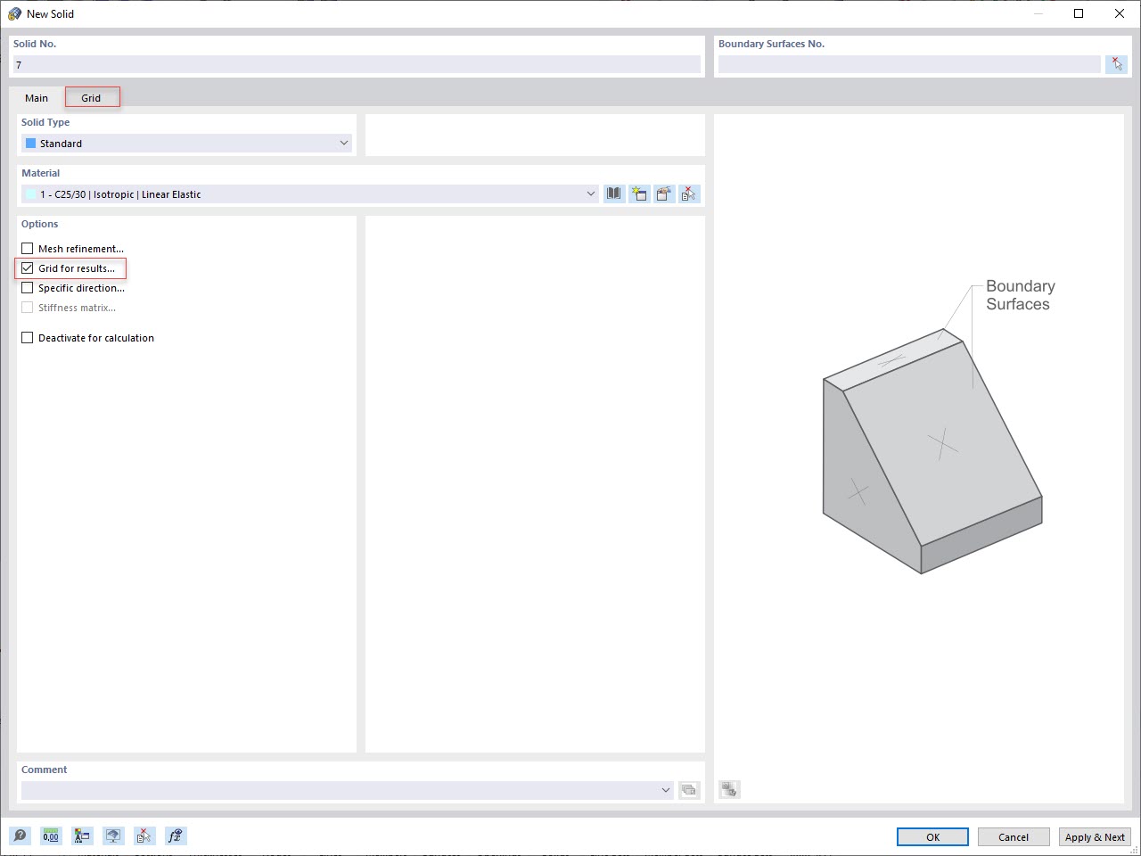
In addition to the "Mesh Refinement" and "Specific Direction" options for solids, you can also activate the "Grid for Results" option, which allows for organizing grid points in the solid space. Among other things, the center of gravity can be set as the origin. There is also the option to activate or deactivate the visibility of the grid for numerical results in "Navigator – Display" under Basic Objects.
Is it also possible to reduce the shear force on a support or perform design with the shear force at a distance d to the support in RF‑CONCRETE Surfaces?
For design with CONCRETE NL, is the creep applied to the entire cross-section, or only to the concrete compression zone?
When I create a user-defined result value, the RFEM solver window opens briefly and the calculation is apparently performed again. Why? I have already performed the calculation.
I am trying to verify RF‑CONCRETE Surfaces based on the results of the example in the manual. Chapter 2.4.3 describes the determination of the statically required reinforcement. Unfortunately, I cannot create an example that exactly represents these results. Can you send me the corresponding example?
Do I have to add the reinforcement for ribs from RF‑CONCRETE Members and RF‑CONCRETE Surfaces?
Is the compression reinforcement calculated for the ultimate limit state design in RF‑CONCRETE Surfaces? Or is it only possible in RF‑CONCRETE Members?


Recommended Products for You
RFEM 6 | Main Program RFEM 6

The new generation of 3D FEA software is used for the structural analysis of members, surfaces, and solids.
Price of First License
4,790.00 USD
RFEM 6 | Additional Analysis

The Nonlinear Material Behavior add-on allows you to consider material nonlinearities in RFEM for example, isotropic plastic, orthotropic plastic, isotropic damage).
Price of First License
1,660.00 USD
RFEM 6 | Additional Analysis

The Structure Stability add-on performs stability analysis of structures. It determines critical load factors and the corresponding stability modes.
Price of First License
1,460.00 USD
RFEM 6 | Additional Analysis

The Construction Stages Analysis (CSA) add-on allows for considering the construction process of structures (member, surface, and solid structures) in RFEM.
Price of First License
1,760.00 USD
RFEM 6 | Additional Analysis

The Time-Dependent Analysis (TDA) add-on allows you to consider the time-dependent material behavior of members and surfaces. The long-term effects, such as creep, shrinkage, and aging, can influence the distribution of internal forces, depending on the structure.
Price of First License
1,160.00 USD
RFEM 6 | Additional Analysis

The Form-Finding add-on finds the optimal shape of members subjected to axial forces and tension-loaded surface models. The shape is determined by the equilibrium between the member axial force or the membrane stress and the existing boundary conditions.
Price of First License
2,320.00 USD
RFEM 6 | Additional Analysis

In RFEM, the Geotechnical Analysis add-on uses properties from soil samples to determine the soil body to be analyzed. The accurate determination of soil conditions significantly affects the quality of the structural analysis of buildings.
Price of First License
1,660.00 USD
RFEM 6 | Special Solutions

The Building Model add-on for RFEM allows you to define and manipulate a building using stories. The stories can be adjusted in many ways afterwards. The information about stories and the entire model (center of gravity) is displayed in tables and graphics.
Price of First License
1,970.00 USD
RFEM 6 | Special Solutions

The two-part Optimization & Costs / CO2 Emission Estimation add-on finds suitable parameters for parameterized models and blocks via the artificial intelligence (AI) technique of particle swarm optimization (PSO) for compliance with common optimization criteria. Furthermore, this add-on estimates the model costs or CO2 emissions by specifying unit costs or emissions per material definition for the structural model.
Price of First License
1,660.00 USD
RFEM 6 | Special Solutions

The Multilayer Surfaces add-on allows you to define multilayer surface structures. The calculation can be carried out with or without the shear coupling.
Price of First License
1,560.00 USD
RFEM 6 | Design

The Stress-Strain Analysis add-on performs general stress analysis by calculating the existing stresses and comparing them with the limit stresses.
Price of First License
1,360.00 USD
RFEM 6 | Design

The Concrete Design add-on allows for various design checks according to international standards. You can design members, surfaces, and columns, as well as perform punching and deformation analyses.
Price of First License
2,970.00 USD
RFEM 6 | Design

The Steel Design add-on performs the ultimate and serviceability limit state design checks of steel members according to various standards.
Price of First License
2,970.00 USD
RFEM 6 | Design

The Timber Design add-on performs the ultimate, serviceability, and fire resistance limit state design checks of timber members according to various standards.
Price of First License
2,170.00 USD
RFEM 6 | Design

The Masonry Design add-on for RFEM allows you to design masonry using the finite element method. It was developed as part of the research project titled DDMaS – Digitizing the Design of Masonry Structures. The material model represents the nonlinear behavior of the brick-mortar combination in the form of macro-modeling.
Price of First License
1,860.00 USD
RFEM 6 | Design

The Aluminum Design add-on performs the ultimate and serviceability limit state design checks of aluminum members according to various standards.
Price of First License
1,970.00 USD
RFEM 6 | Joints
.png?mw=600&hash=49b6a289915d28aa461360f7308b092631b1446e)
The Steel Joints add-on for RFEM allows you to analyze steel connections using an FE model. The FE model is generated automatically in the background and can be controlled via the simple and familiar input of components.
Price of First License
2,670.00 USD