- CO1=LC2
- CO2=LC1+LC2
- RC2*=CO1 or CO2
Question
Which result combinations can I design with the RF‑/JOINTS Pro program, and what should I pay attention to?
Answer:
The RF-/JOINTS add-on module is divided into several joint groups. For this, see the following FAQ.Therefore, there is no straightforward answer to the special aspects of the design as in this FAQ.
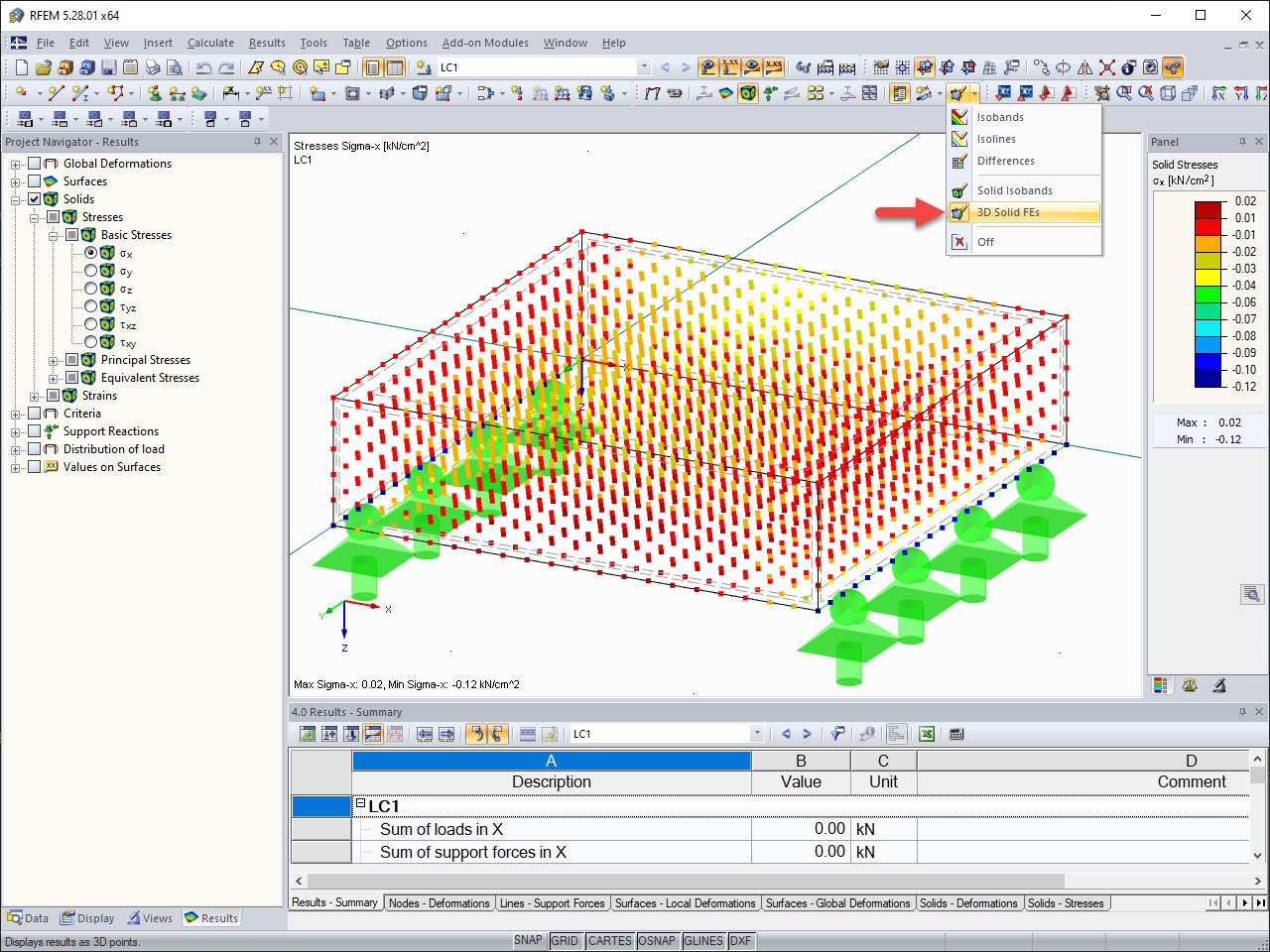
In contrast to the RF‑/TIMBER Pro add-on module described in the mentioned FAQ, however, it is obvious that the RF‑/JOINTS add-on modules cannot design EC2, even if manually changing the LDC; for example, in the RF‑/JOINTS Timber - Steel to Timber add-on module (see Image 01).
Furthermore, this also applies to the add‑on modules RF̩GLASS and RF‑/CONCRETE NL.
The reason for this is that there are stiffnesses exported in the program in the case of some joint groups of the RF‑/JOINTS add‑on module. For nonlinear calculations, the superposition with result combinations is not allowed. In the case of the second result combination mentioned above, there is the special feature that the superposition is no longer conservative, even in the case of simple structures. The design also cannot be performed correctly by manually changing the LDC.
Nevertheless, if a result combination should be superimposed with constant and alternative additive, it is necessary to split EC2 in the attached file into load combinations as follows.
Author
Mr. Kuhn is responsible for developing products for timber structures, and provides technical support for our customers.
Do you have any questions?
![KB 001883 | Plate Girder Design According to AISC 360-22 in RFEM 6](/en/webimage/051561/3980997/im1.png?mw=512&hash=b8237709c4f30213fac51d86d32a42bddde72f03)
Plate girder is an economical choice for long spans construction. I-section steel plate girder typically has a deep web to maximize its shear capacity and flange separation, yet thin web to minimize the self-weight. Due to its large height-to-thickness (h/tw) ratio, transverse stiffeners may be required to stiffen the slender web.
![Steel Connection Rigidity and Its Influence on Structural Design](/en/webimage/051432/3972404/Rigidity-caseA.png?mw=512&hash=3be64e68ab2956fd2b92f0afa1559b3a8c72b468)
Understanding steel connection rigidity is crucial in structural design. Often, connections are treated as strictly pinned or rigid, but this can lead to uneconomical or even dangerous designs. Explore how Dlubal Software's RFEM and Steel Joints add-on help verify connection stiffness and moment resistance, ensuring safer and more economical designs.
![Timber Panel Wall Stiffnesses](/en/webimage/049956/3893282/49956.png?mw=512&hash=8dfc2b6d0af6ade74073e21655c6a73a34a77751)
In this article, the calculation of a timber panel wall with the beam panel thickness type is compared with a manual calculation.
![KB 001848 | Timber Column Design as per the 2018 NDS Standard in RFEM 6](/en/webimage/040983/3525158/Timber_Column_for_KB_1848.png?mw=512&hash=8767c3300658d77c253bb7ff632327937a04dd95)
Using the Timber Design add-on, timber column design is possible according to the 2018 NDS standard ASD method. Accurately calculating timber member compressive capacity and adjustment factors is important for safety considerations and design. The following article will verify the maximum critical buckling strength calculated by the Timber Design add-on using step-by-step analytical equations as per the NDS 2018 standard including the compressive adjustment factors, adjusted compressive design value, and final design ratio.
![Add-on "Steel Joints for RFEM 6" | Component Library](/en/webimage/043097/3898884/steel_joints_components.png?mw=512&hash=e4f835906155863fc7019d5043b22e553dc766f9)
- Numerous component types, such as base and end plates, web angles, fin plates, gusset plates, stiffeners, tapers, or ribs for easy input of typical connection situations
- Universally applicable basic components (such as plates, welds, bolts, auxiliary planes) for modeling complex connection situations
- Graphical display of the connection geometry with dynamic updating during the input
- Wide range of cross-section shapes: I-sections, U-sections, angles, T-sections, hollow sections, built-up cross-sections and thin-walled sections
- Library in the Dlubal Center with a large number of program-side template connections, including user-defined templates
- Automatic adaptation of the connection geometry based on the relative arrangement of the components to each other – even in case of subsequent editing of the structural components
![Feature 002824 | OSB Material for USA and Canada](/en/webimage/050460/3955503/2024-06-28_10-42-39.png?mw=512&hash=5ec86ff7955d8c9a50e53301df3f21fceda009a5)
In RFEM, the oriented strand board (OSB) material is available for the USA and Canada. The material parameters are taken from the "Panel Design Specification manual".
![Feature 002820 | Limit Plastic Strain for Welds](/en/webimage/050344/3881226/1.png?mw=512&hash=9d7f6c198b6d4ae6ee8f2fa8bca75f85579e14c9)
In the ultimate configuration of the steel joint design, you have the option to modify the limit plastic strain for welds.
![Component "Base Plate"](/en/webimage/050345/3936120/50345.png?mw=512&hash=3bd641cb1a2445804b338855e4debfc40c6563e9)
The "Base Plate" component allows you to design base plate connections with cast-in anchors. In this case, plates, welds, anchorages, and steel-concrete interaction are analyzed.
Recommended Products for You