
Question:
How can I rotate a nodal support using the COM interface?
Answer:
The rotation of a nodal support is defined by means of a user-defined coordinate system. In the following example, a nodal support is rotated by 45 ° about the z-axis.
Question:
How can I rotate a nodal support using the COM interface?
Answer:
The rotation of a nodal support is defined by means of a user-defined coordinate system. In the following example, a nodal support is rotated by 45 ° about the z-axis.


.png?mw=512&hash=a2d64046b1b82d01d353d39d4a145023e6992bce)
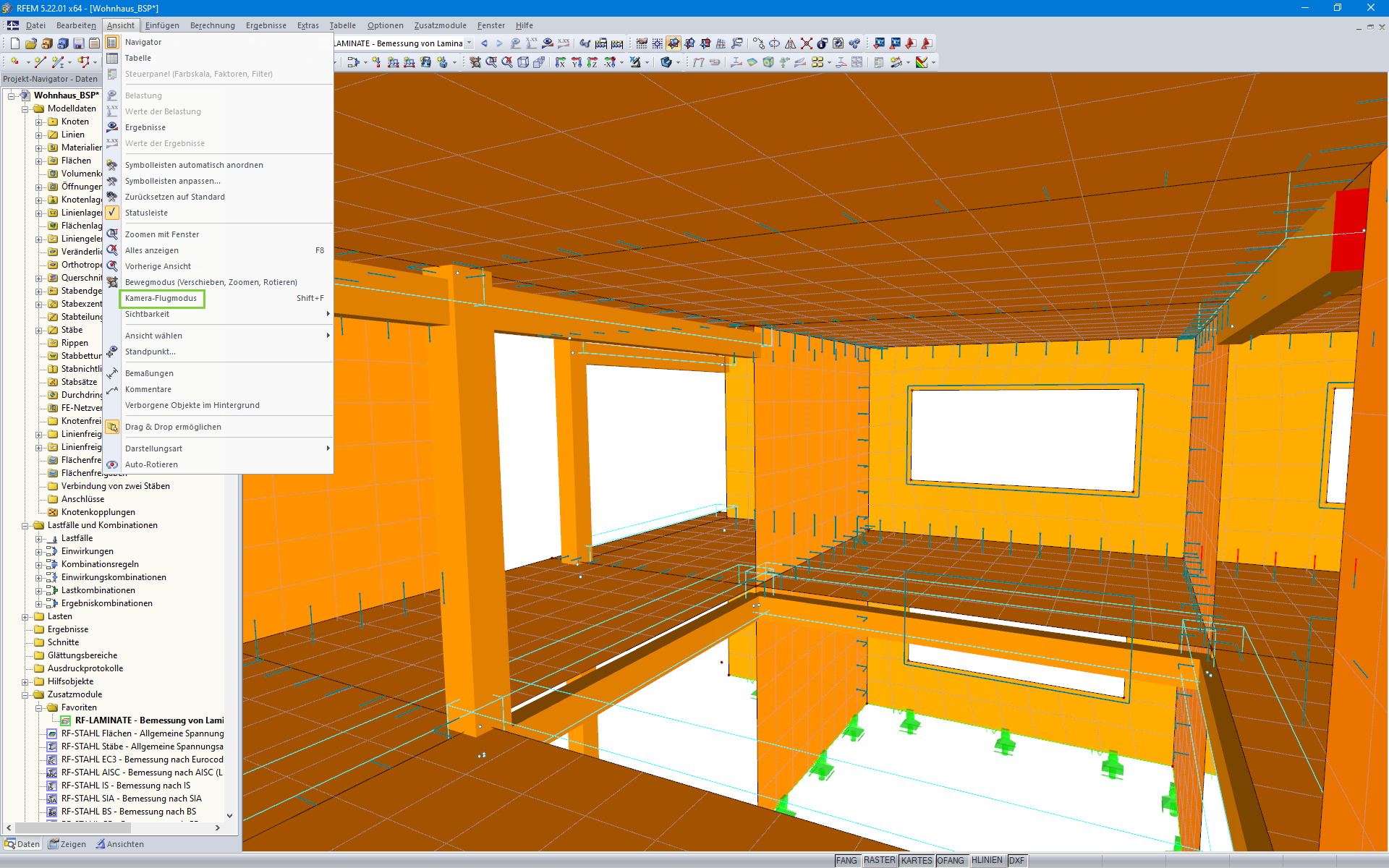
With the Camera Fly Mode view option, you can fly through your RFEM and RSTAB structure. Control the direction and speed of the flight with your keyboard. Additionally, you can save the flight through your structure as a video.

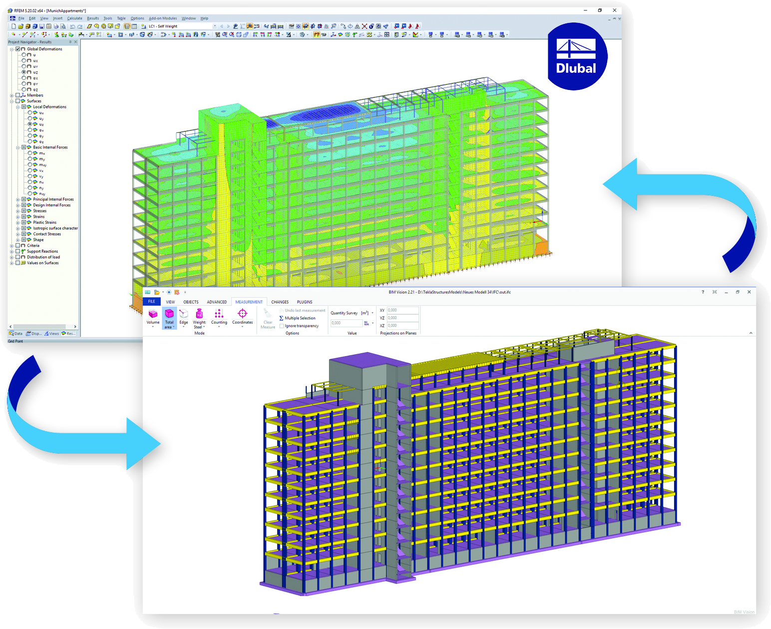
The result tables show in color whether the internal forces are positive or negative, as well as showing the relation to the extreme values. The result tables of the design modules use color scales to represent the respective design ratios. This way, the governing locations are apparent immediately.

The deformation process of the global deformation components can be represented as a movement sequence.

Result values for deformations, internal forces, stresses, and so on, can be displayed on the isolines.
Is it possible to consider shear panels and rotational restraints in the global calculation?
How can I analyze support reactions on line supports of surfaces?
Are the result sections helpful?


