A cylindrical membrane is stretched using isotropic prestress. Find the final minimal shape of the membrane - catenoid. Determine the maximum radial deflection of the membrane. The add-on module RF-FORM-FINDING is used for this purpose. Elastic deformations are neglected both in RF-FORM-FINDING and in analytical solution, also self-weight is neglected in this example.
| 5 star | ||
| 4 star | ||
| 3 star | ||
| 2 star | ||
| 1 star |
Verification Example 000207 | 1
| Number of Nodes | 6 |
| Number of Lines | 3 |
| Number of Surfaces | 1 |
| Number of Load Cases | 1 |
| Total Weight | 0.007 tons |
| Dimensions (Metric) | 3.654 x 3.643 x 2.654 m |
| Dimensions (Imperial) | 11.99 x 11.95 x 8.71 feet |
| Program Version | 5.15.01 |
You can download this structural model to use it for training purposes or for your projects. However, we do not assume any guarantee or liability for the accuracy or completeness of the model.
.png?mw=512&hash=4a84cbc5b1eacf1afb4217e8e43c5cb50ed8d827)
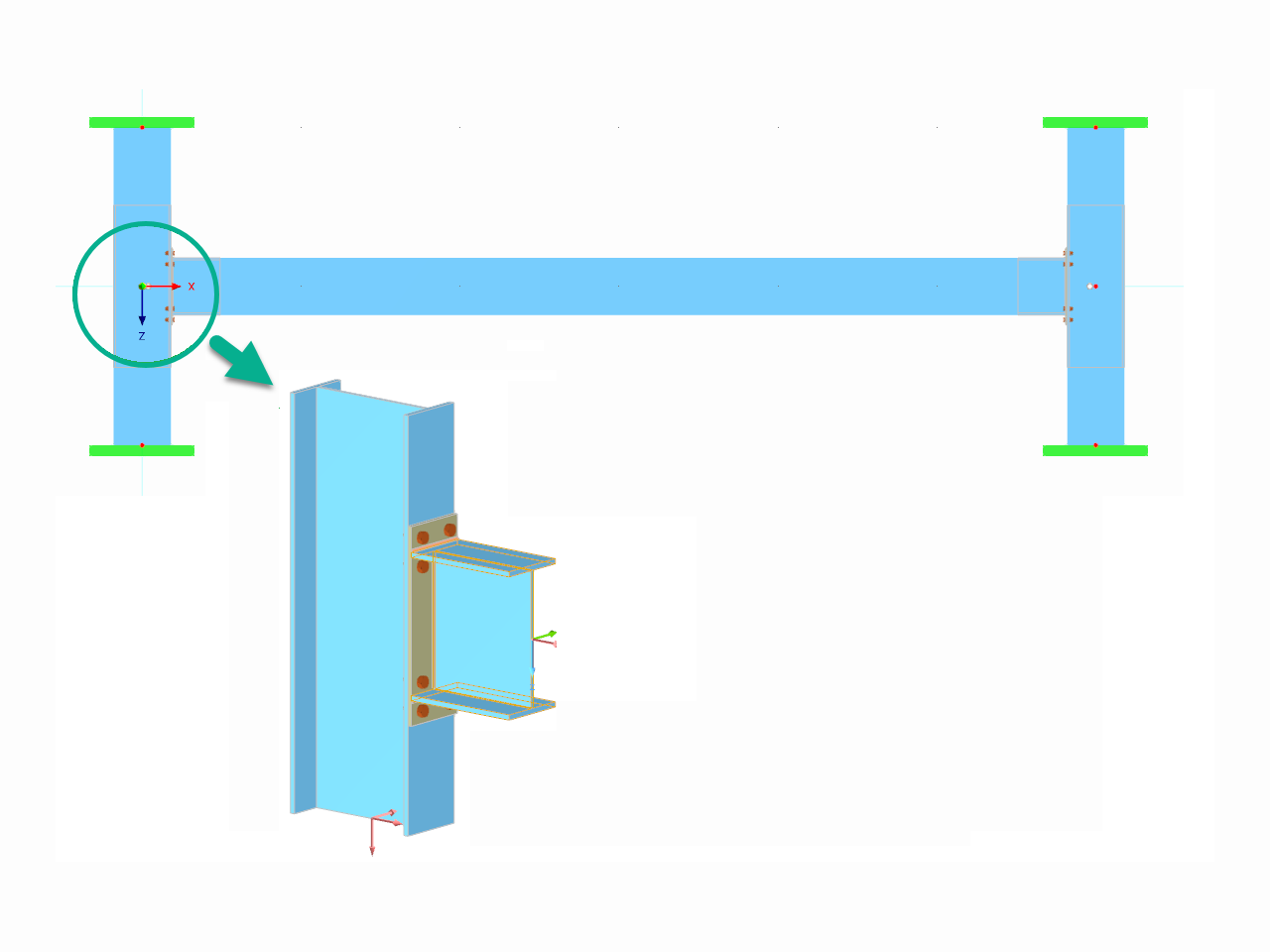
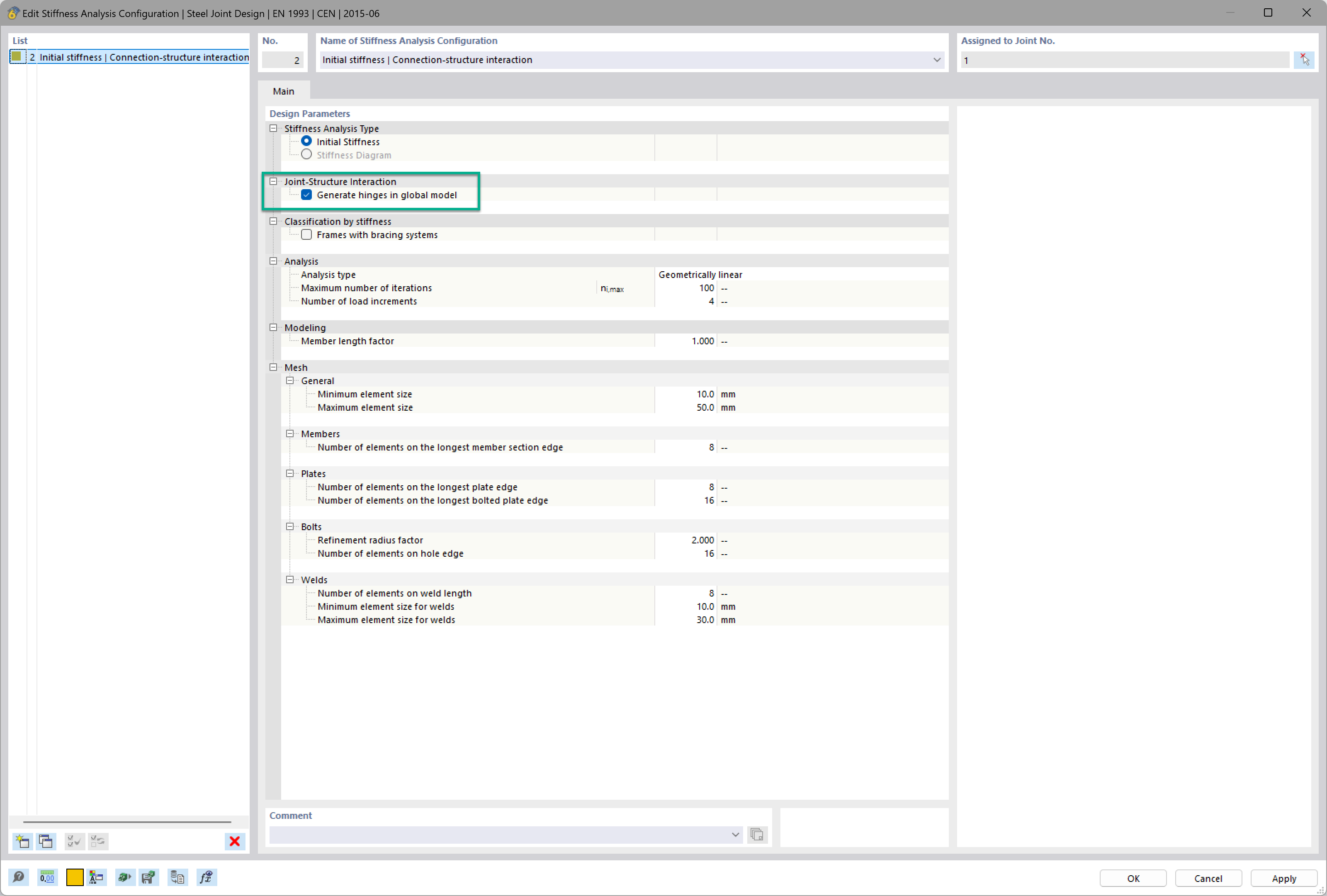
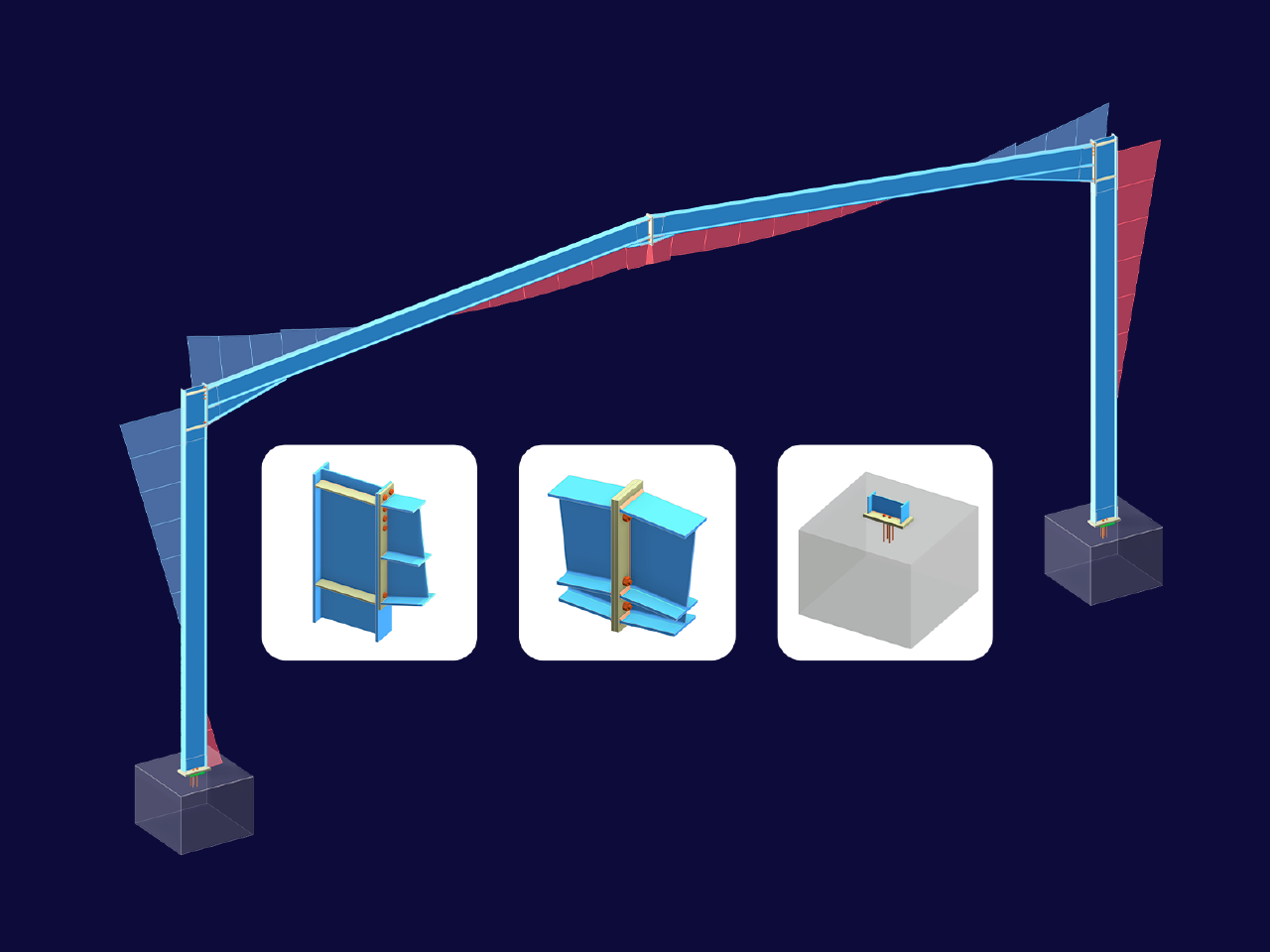
Want to automatically consider steel joint stiffness in your global RFEM model? Utilize the Steel Joints add-on!
Activate joint-structure interaction in the stiffness analysis of your steel joints. Hinges with springs are then automatically generated in the global model and included in subsequent calculations.
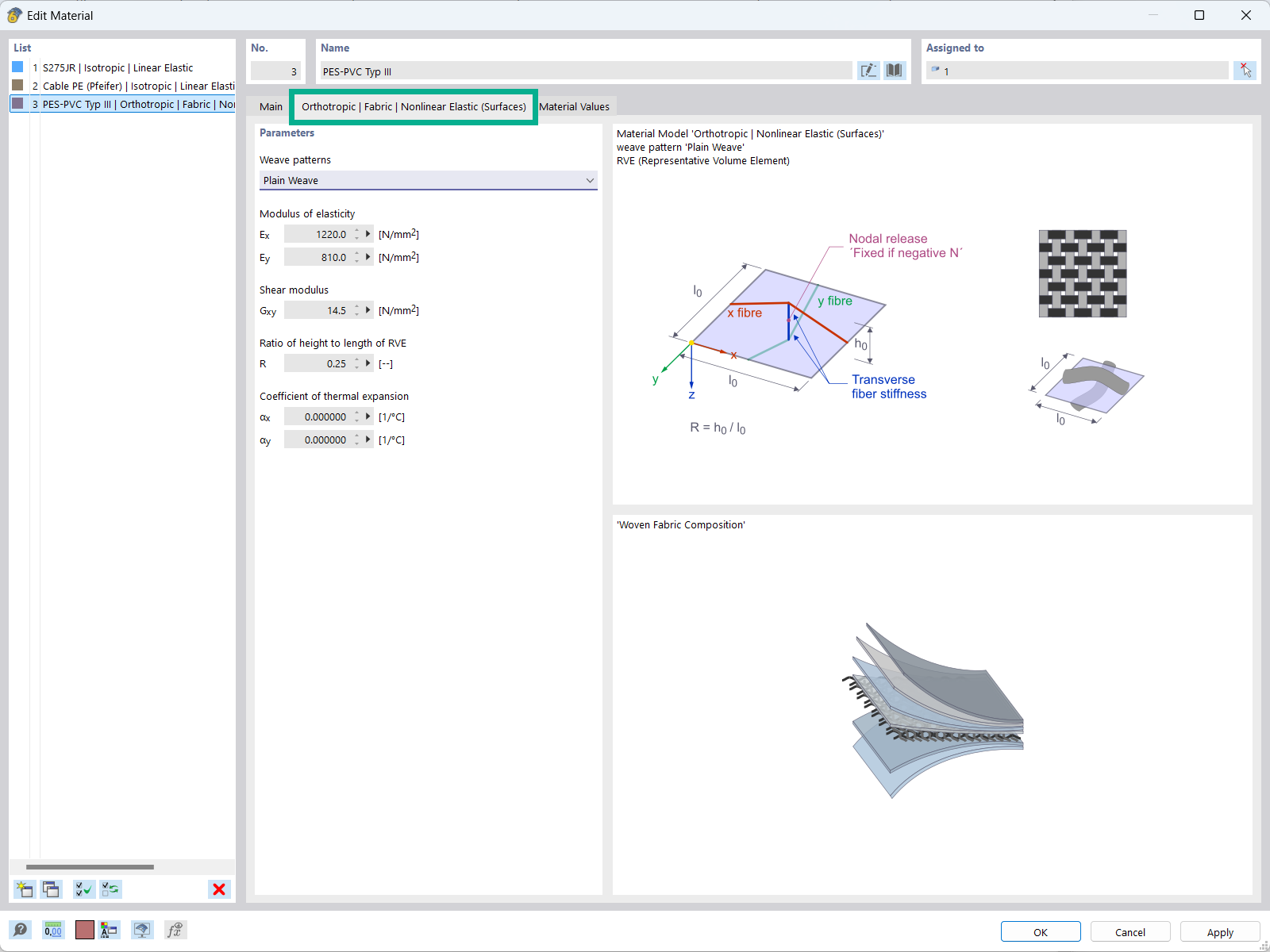
The "Orthotropic | Fabric | Nonlinear Elastic (Surfaces)" material model allows you to define prestressed fabric membranes using the representative microstructure-solid element model – RVE.
By considering the fabric geometry in the microstructure model, the corresponding transversal strain effect can now be considered for all force conditions in the membrane.
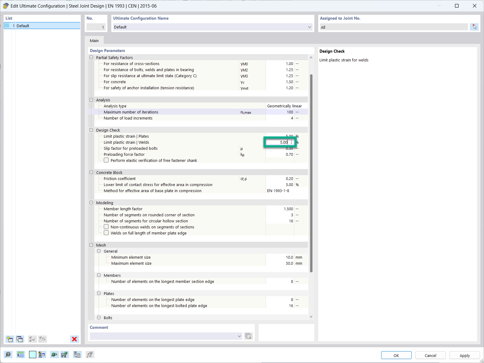
In the ultimate configuration of the steel joint design, you have the option to modify the limit plastic strain for welds.
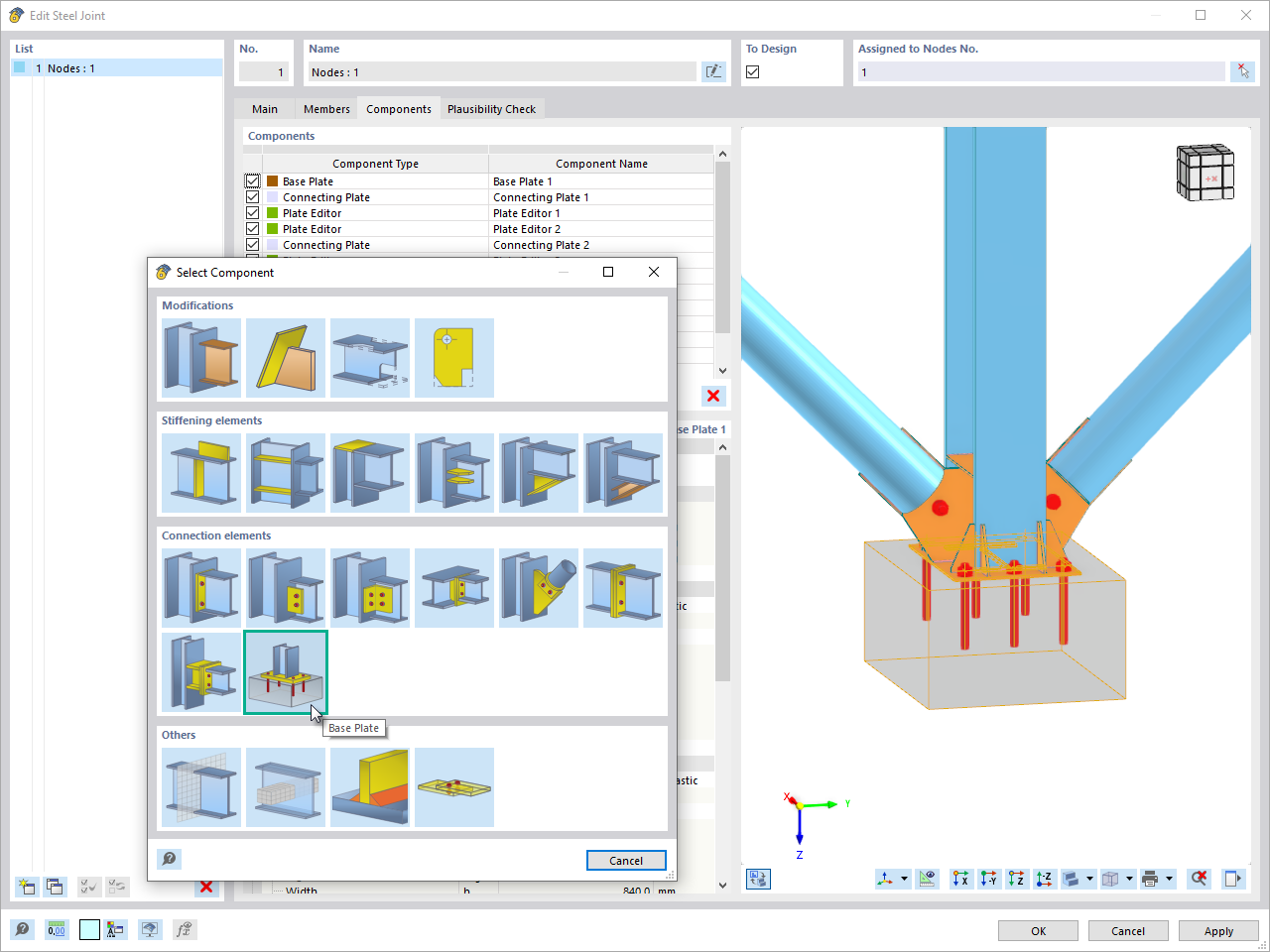
The "Base Plate" component allows you to design base plate connections with cast-in anchors. In this case, plates, welds, anchorages, and steel-concrete interaction are analyzed.
In the Steel Joints add-on, I get high utilization ratios for preloaded bolts in the tension design. Where do these high utilization ratios come from and how can I evaluate the load-bearing reserves of the bolt?
How can I fix the error warning “10060 - The structure is unstable” for modal analysis instability?
How can treating a connection as fully rigid result in an uneconomical design?
Is it possible to consider shear panels and rotational restraints in the global calculation?
I am calculating a support that is clamped at the base, held in the X direction at the head, and can buckle in the Y direction. I have set the bar shear lengths using node carriers. In the verification, the buckling length values for the calculation are the same, L_(cr,z) = L_(cr,y) = 2.41 m. What am I doing wrong?


.png?mw=350&hash=c6c25b135ffd26af9cd48d77813d2ba5853f936c)


_1.jpg?mw=350&hash=ab2086621f4e50c8c8fb8f3c211a22bc246e0552)


.png?mw=600&hash=49b6a289915d28aa461360f7308b092631b1446e)


