Safe pipelines are available for you here. RF-PIPING Design is used for the precise design of pipelines. The module compares the existing pipe stresses with the allowable stresses according to ASME B31.1 and ASME B31.3, among other standards.
Add-on Module RF-PIPING Design for RFEM 5


Duration: 01:07:09 min

Duration: 01:05:28 min

Duration: 00:45:08 min

Duration: 00:01:00 min

Duration: 00:00:50 min

Duration: 00:00:45 min

Duration: 00:00:24 min

Duration: 00:00:34 min

Duration: 00:00:53 min


The weld stresses between surfaces can be determined using the Stress-Strain Analysis add-on in RFEM 6. Furthermore, the stress limit determined according to the applicable standard can be input to determine the stress ratio of the weld. This article focuses on the fillet weld design according to AISC 360-22 [1] with two examples from AISC Volume 1: Design Examples [2].

This technical article addresses the direct deformation analysis of reinforced concrete beams considering the long-term effects of creep and shrinkage. The direct calculation according to Eurocode 2 (EN 1992-1-1, Section 7.4.3) is explained using a single-span beam. Particular emphasis is placed on tension stiffening, behavior in the cracked state based on the distribution factor (damage parameter), and consideration of shrinkage and creep behavior.

According to AISC Design Guide 9 Section 4.1 [1], the following torsional stresses must be considered for open cross-sections subjected to warping:
Using the Timber Design add-on, timber column design is possible according to the 2018 NDS standard ASD method. Accurately calculating timber member compressive capacity and adjustment factors is important for safety considerations and design. The following article will verify the maximum critical buckling strength calculated by the Timber Design add-on using step-by-step analytical equations as per the NDS 2018 standard including the compressive adjustment factors, adjusted compressive design value, and final design ratio.


In the Stress-Strain Analysis add-on, you can use the option to specify sign-dependent limit stresses by stress component.

Get a better understanding of the stress distribution within member cross-sections by using clipping planes.

The deformation process of the global deformation components can be represented as a movement sequence.
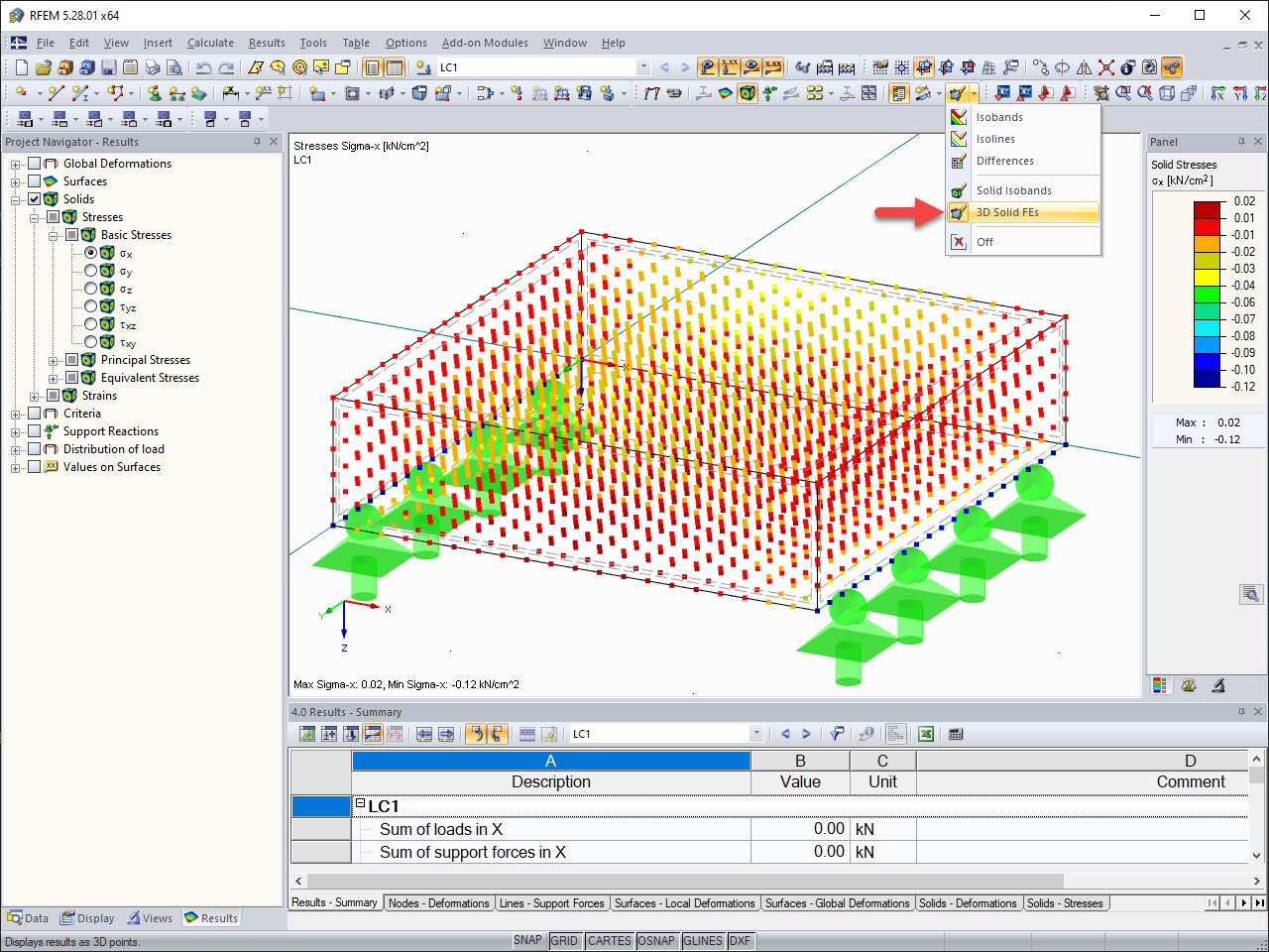
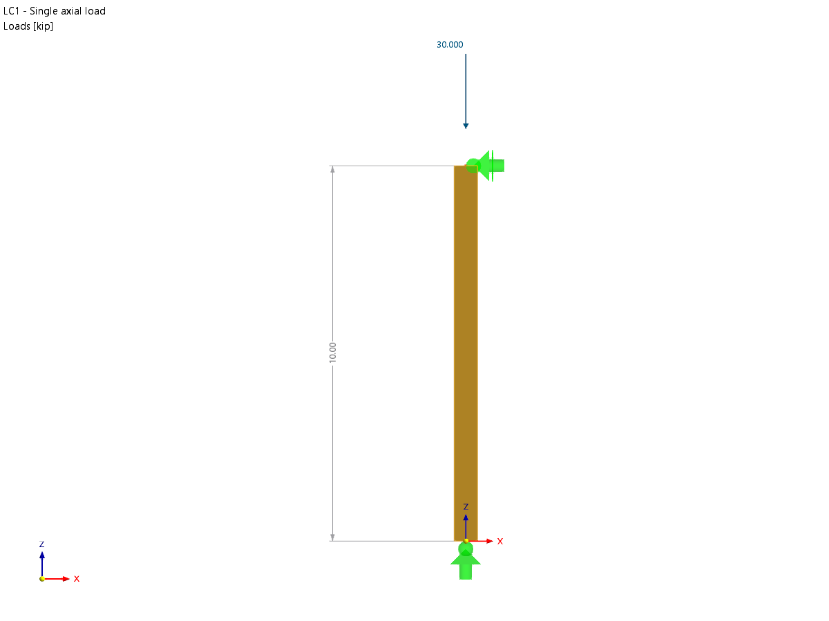
The results of solid stresses can be displayed as colored 3D points in the finite elements.
Why are the stresses of the structural analysis different from those calculated with the Stress-Strain Analysis add-on?
The limit stress is activated, but my stress ratio is “non-designable” in the Stress-Strain Analysis add-on. What could be the reason?
Is it possible to display the deformation analysis of a surface (limit 0.5‰)?
Is it possible to perform stability analysis according to EN 1999‑1‑1 in RSECTION 1?
Is it possible to perform stability analysis according to EN 1993‑1‑1 in RSECTION 1?
Is it possible to consider the eccentricity of unsymmetrical line welds for the stress analysis in RFEM 6?


-querkraft-hertha-hurnaus.jpg?mw=350&hash=3306957537863c7a7dc17160e2ced5806b35a7fb)
