- Design of members and sets of members for tension, compression, bending, shear, combined internal forces, and torsion
- Stability analysis of buckling and lateral-torsional buckling
- Automatic determination of critical buckling loads and critical buckling moments for general load applications and support conditions by means of a special FEA program (eigenvalue analysis) integrated in the module
- Alternative analytical calculation of the critical buckling moment for standard situations
- Optional application of discrete lateral supports to beams and continuous members
- Automatic cross-section classification (compact, noncompact, and slender)
- Serviceability limit state design (deflection)
- Cross-section optimization
- A wide range of available cross-sections, such as rolled I-sections, channel sections, T-sections, angles, rectangular and circular hollow sections, round bars, symmetrical, asymmetrical, parameterized I-, T-, and angle sections, as well as user-defined SHAPE‑THIN sections
- Clearly arranged input and result windows
- Detailed result documentation including references to design equations of the used standard
- Various filter and sorting options of results including result lists by member, cross-section, x-location, or by load cases, load and result combinations
- Result table of member slenderness and governing internal forces
- Parts list with weight and solid specifications
- Seamless integration in RFEM/RSTAB
- Metric and imperial units
RF-/STEEL AS | Features
_(2)_(1).png?mw=1024&hash=ed67cf492a6214a737cf416b358242cedd959ab6)


Duration: 00:00:55 min

Duration: 00:01:00 min
Duration: 00:00:55 min

Duration: 00:00:48 min

Duration: 00:01:49 min

Duration: 00:00:46 min

Duration: 00:00:31 min

Duration: 00:00:50 min

Duration: 00:00:34 min
.png?mw=350&hash=5c4b2144aa52cd2928e41d7b311671dea882afa3)


Shrinkage and creep are time-dependent deformation properties of concrete that usually have to be considered in the serviceability limit state design.

Different methods are available for calculating the deformation in the cracked state. RFEM provides an analytical method according to DIN EN 1992-1-1 7.4.3 and a physical-nonlinear analysis. Both methods have different features and can be more or less suitable depending on the circumstances. This article will give an overview of the two calculation methods.

Performing serviceability limit state design also includes taking into account the allowable deformation. Calculating the deformation of reinforced concrete components depends on whether or not the observed cross-section cracks under the applied loading. The governing control parameter in RF-CONCRETE Deflect is the distribution coefficient ζ.

For reinforced concrete components and structures whose structural behavior is significantly influenced by the second-order effects, Eurocode 2 provides the general method based on a nonlinear determination of internal forces according to the second-order analysis (5.8.6), as well as an approximation method based on the nominal curvature (5.8.8).
The aim of this technical article is to perform a design according to the general design method of Eurocode 2, using the example of a slender reinforced concrete column.
The aim of this technical article is to perform a design according to the general design method of Eurocode 2, using the example of a slender reinforced concrete column.


The deformation analysis according to the approximation method defined in standards (for example, deformation analysis according to EN 1992‑1‑1, 7.4.3) applies to the calculation of "effective stiffnesses" in the finite elements in accordance with the existing limit state of the concrete with or without cracks. These stiffnesses are used to determine the surface deformation by repeated FEM calculation.
The effective stiffness calculation of finite elements takes into account a reinforced concrete cross-section. Based on the internal forces determined for the serviceability limit state in RFEM, the program classifies the reinforced concrete cross-section as 'cracked' or 'uncracked'. If the tension stiffening at a section should be considered as well, a distribution coefficient (according to EN 1992-1-1, Eq. 7.19, for example) is used. The material behavior for the concrete is assumed to be linear-elastic in the compression and tension zone until the concrete tensile strength is reached. This is reached exactly in the serviceability limit state.
When determining the effective stiffnesses, creep and shrinkage are taken into account at the "cross-section level". The influence of shrinkage and creep in statically indeterminate systems is not taken into account in this approximation method (for example, tensile forces from shrinkage strain in systems restrained on all sides are not determined and must be considered separately). In summary, RF-CONCRETE Deflect calculates deformations in two steps:
- Calculation of effective stiffnesses of the reinforced concrete cross-section assuming linear-elastic conditions
- Calculation of the deformation using the effective stiffnesses with FEM

After the calculation, the module shows clearly arranged tables listing the deformation analysis results. All intermediate values are displayed in a comprehensible manner. Graphical representation of design ratios and deformation in RFEM allows a quick overview of critical areas.
Since the design results are displayed by surface or by point including all intermediate results, you can retrace all details of the calculation. The complete integration of results in the RFEM printout report guarantees verifiable structural design.

- Deformation analyses of reinforced concrete surfaces without or with cracks (state II) by applying the approximation method (for example, deformation analysis according to EN 1992-1-1, Cl. 7.4.3 )
- Tension stiffening of concrete applied between cracks
- Optional consideration of creep and shrinkage
- Graphical representation of results integrated in RFEM; for example, deformation or sag of a flat slab
- Numerical results clearly arranged in tables and graphical display of the results in the model
- Complete integration of results in the RFEM printout report
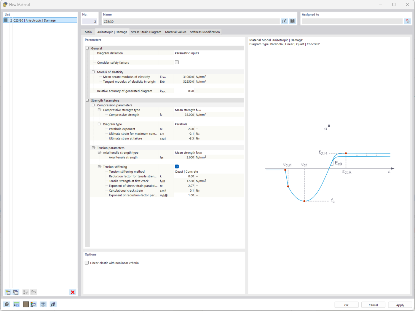
The "Nonlinear Material Behavior" add-on includes the Anistropic | Damage material model for concrete structural components. This material model allows you to consider concrete damage for members, surfaces, and solids.
You can define an individual stress-strain diagram via a table, use the parametric input to generate the stress-strain diagram, or use the predefined parameters from the standards. Furthermore, it is possible to consider the tension stiffening effect.
For the reinforcement, both nonlinear material models "Isotropic | Plastic (Members)" and "Isotropic | Nonlinear Elastic (Members)" are available.
It is possible to consider the long-term effects due to creep and shrinkage using the "Static Analysis | Creep & Shrinkage (Linear)" analysis type that has been recently released. Creep is taken into account by stretching the stress-strain diagram of the concrete using the factor (1+phi), and shrinkage is taken into account as the pre-strain of the concrete. More detailed time step analyses are possible using the "Time-Dependent Analysis (TDA)" add-on.
What is the maximum number of reinforcement groups that can be created in a design case in RF‑CONCRETE Surfaces?
When switching from the manual definition of the reinforcement areas to the automatic arrangement of the reinforcement according to window 1.4, the result of the deformation calculation changes, although the basic reinforcement has not been changed. What makes this change?
Is it possible to perform design without an additional reinforcement in RF‑CONCRETE Surfaces?
I obtain different results when comparing the deformation analysis in the RF‑CONCRETE add-on modules and another calculation program. What could be the reason for this?
Which tensile strength of concrete is used for the transition from State I to State II? fctm or fct;0.05?
Is it possible to define the damage parameter ζ manually for the calculation with RF‑CONCRETE Deflect? In such a way that it should always be at least 0.5?

_1.jpg?mw=350&hash=ab2086621f4e50c8c8fb8f3c211a22bc246e0552)


-querkraft-hertha-hurnaus.jpg?mw=350&hash=3306957537863c7a7dc17160e2ced5806b35a7fb)


Recommended Products for You
RFEM 6 | Main Program RFEM 6

The new generation of 3D FEA software is used for the structural analysis of members, surfaces, and solids.
Price of First License
4,790.00 USD
RFEM 6 | Design

The Concrete Design add-on allows for various design checks according to international standards. You can design members, surfaces, and columns, as well as perform punching and deformation analyses.
Price of First License
2,970.00 USD
RFEM 6 | Additional Analysis

The Construction Stages Analysis (CSA) add-on allows for considering the construction process of structures (member, surface, and solid structures) in RFEM.
Price of First License
1,760.00 USD
RFEM 6 | Additional Analysis

In RFEM, the Geotechnical Analysis add-on uses properties from soil samples to determine the soil body to be analyzed. The accurate determination of soil conditions significantly affects the quality of the structural analysis of buildings.
Price of First License
1,660.00 USD
RFEM 6 | Dynamic Analysis

The Modal Analysis add-on allows for the calculation of eigenvalues, natural frequencies, and natural periods for member, surface, and solid models.
Price of First License
1,360.00 USD
RFEM 6 | Dynamic Analysis

The Response Spectrum Analysis add-on performs seismic analysis using multi-modal response spectrum analysis. The spectra required for this can be created in compliance with the standards or can be user-defined. The equivalent static forces are generated from them. The add-on includes an extensive library of accelerograms from seismic zones that can be used to generate the response spectra.
Price of First License
1,560.00 USD
RFEM 6 | Dynamic Analysis

Using the Pushover Analysis add-on, you can analyze the seismic actions on a particular building, and thus assess whether the building can withstand an earthquake.
Price of First License
1,460.00 USD
RFEM 6 | Special Solutions

The Building Model add-on for RFEM allows you to define and manipulate a building using stories. The stories can be adjusted in many ways afterwards. The information about stories and the entire model (center of gravity) is displayed in tables and graphics.
Price of First License
1,970.00 USD
RFEM 6 | Design

With the Concrete Foundations add-on, you can design square and rectangular individual foundations. In addition to the reinforced concrete design, geotechnical verifications are also carried out. You also determine automatic reinforcement suggestions and receive detailed reinforcement plans and 3D renderings of the foundation structures.
Price of First License
1,260.00 USD
RFEM 6 | Design

The Masonry Design add-on for RFEM allows you to design masonry using the finite element method. It was developed as part of the research project titled DDMaS – Digitizing the Design of Masonry Structures. The material model represents the nonlinear behavior of the brick-mortar combination in the form of macro-modeling.
Price of First License
1,860.00 USD