Unfortunately, it is not possible for the line supports to define a variable spring by means of the support length. In this case, you should set nodal supports in a sufficiently fine division and assign different spring stiffnesses to them. When placing nodal supports on a line, a node is always required. This node is also an FE restrained node, which means: an FE node is also created automatically at this node.
Variable Spring Stiffness in Line Supports
I would like to put a plate on a line support with spring stiffness varying linearly about the line support length. Is there any option in RFEM to model this precise case?
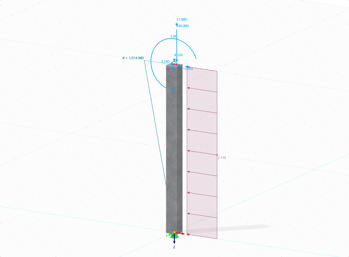
The aim of this technical article is to perform a design according to the general design method of Eurocode 2, using the example of a slender reinforced concrete column.

.png?mw=512&hash=4a84cbc5b1eacf1afb4217e8e43c5cb50ed8d827)
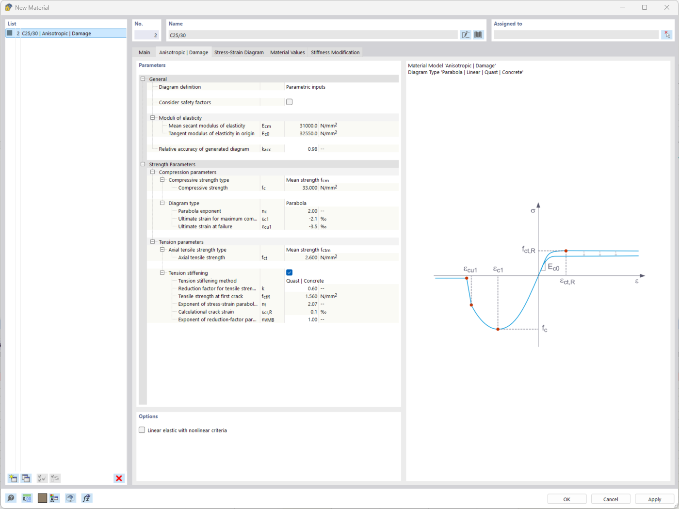
The "Nonlinear Material Behavior" add-on includes the Anistropic | Damage material model for concrete structural components. This material model allows you to consider concrete damage for members, surfaces, and solids.
You can define an individual stress-strain diagram via a table, use the parametric input to generate the stress-strain diagram, or use the predefined parameters from the standards. Furthermore, it is possible to consider the tension stiffening effect.
For the reinforcement, both nonlinear material models "Isotropic | Plastic (Members)" and "Isotropic | Nonlinear Elastic (Members)" are available.
It is possible to consider the long-term effects due to creep and shrinkage using the "Static Analysis | Creep & Shrinkage (Linear)" analysis type that has been recently released. Creep is taken into account by stretching the stress-strain diagram of the concrete using the factor (1+phi), and shrinkage is taken into account as the pre-strain of the concrete. More detailed time step analyses are possible using the "Time-Dependent Analysis (TDA)" add-on.
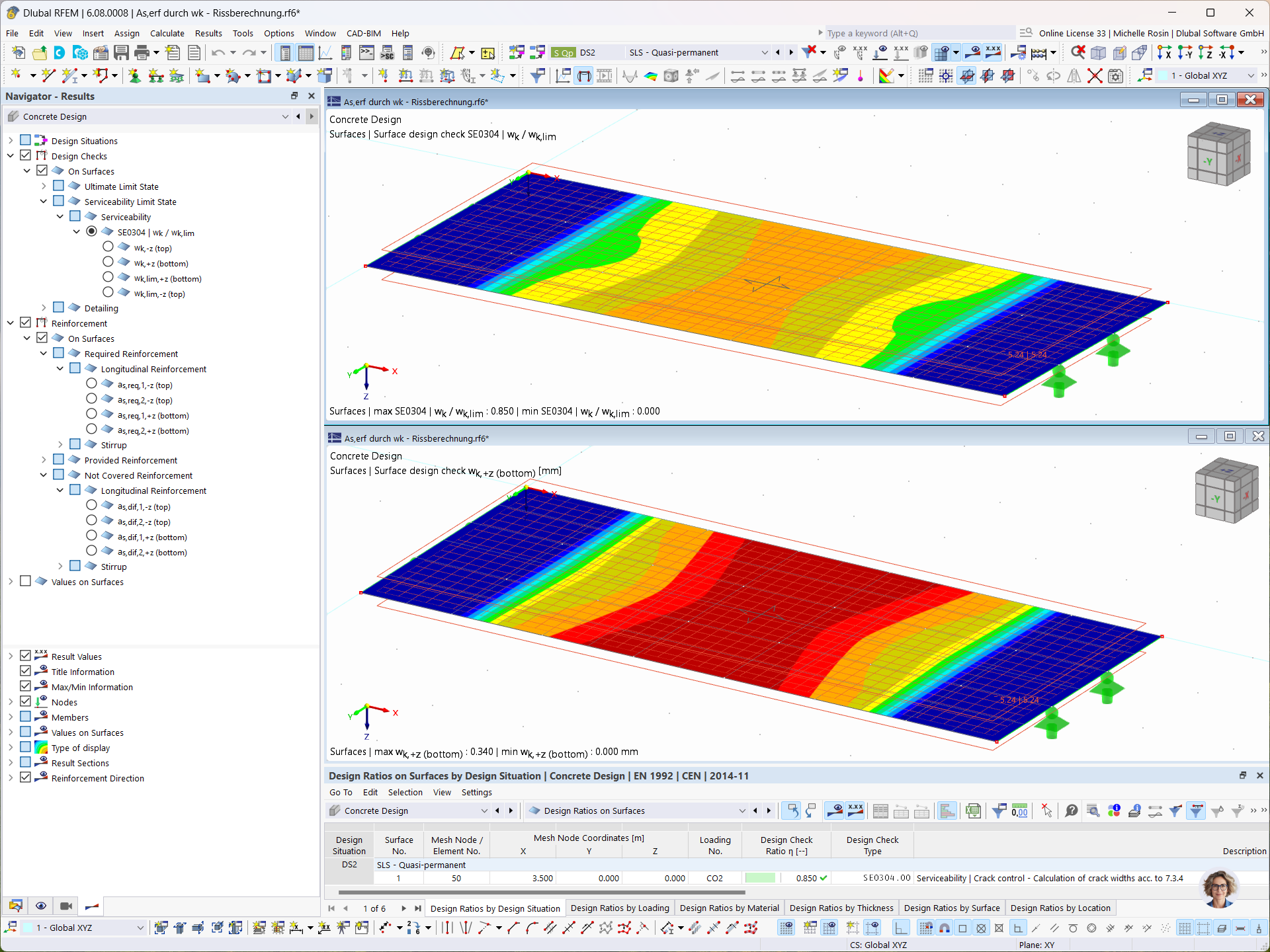
In the Concrete Design add-on, you can determine the required longitudinal reinforcement for the direct crack width analysis (w k).

For the design of reinforced concrete members, there is the option to automatically determine the number or diameter of rebars.
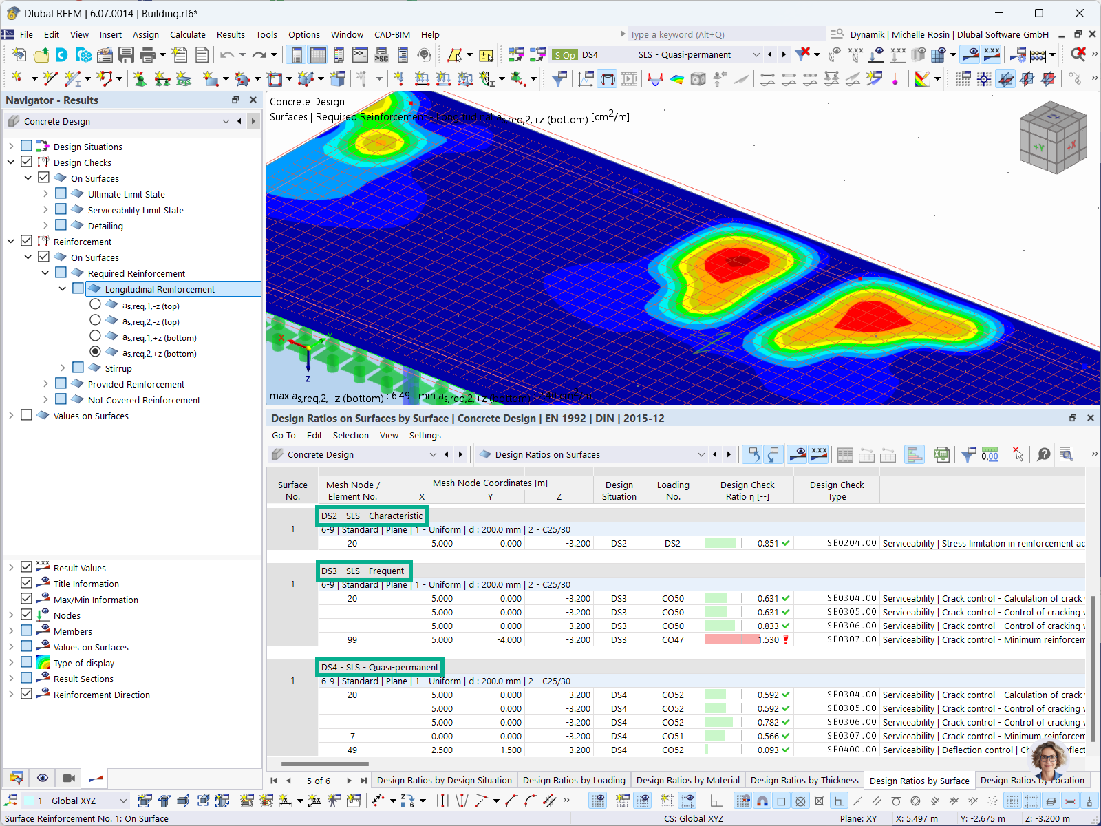
For concrete design, you can display the reinforcement results in tables separately by design situation.
Why is the effective depth different with the effective depth used in shear checks?
How can I check the determination of the required reinforcement?


_1.jpg?mw=350&hash=ab2086621f4e50c8c8fb8f3c211a22bc246e0552)


-querkraft-hertha-hurnaus.jpg?mw=350&hash=3306957537863c7a7dc17160e2ced5806b35a7fb)


