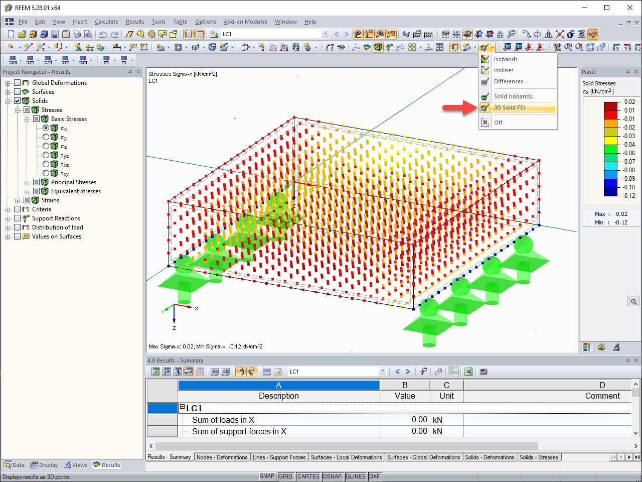
The stresses in the cross‑section of the member are calculated in the so‑called stress points. These points are set at such locations in the cross‑section, at which the extreme values for the stresses due to the loading types can occur in the material.
KB 000616 | Stress Points for Shear Stresses
Links
.png?mw=512&hash=4a84cbc5b1eacf1afb4217e8e43c5cb50ed8d827)
This article provides a comprehensive overview of essential seismic analysis methods, explaining their principles and applications, as well as the scenarios in which they are most effective

The properties of the connection between a reinforced concrete slab and a masonry wall can be correctly considered in the modeling using a special line hinge that is available in RFEM 6. This article will show you how to define this type of hinge using a practical example.

You can model and analyze masonry structures in RFEM 6 with the Masonry Design add-on that employs the finite element method for the design. Complex masonry structures can be modeled, and static and dynamic analysis can be performed, given that a nonlinear material model is implemented in the program to display the load-bearing behavior of masonry and the different failure mechanisms. You can enter and model masonry structures directly in RFEM 6 and combine the masonry material model with all common RFEM add-ons. In other words, you can design entire building models in connection with masonry.

The effects due to snow load are described in the American standard ASCE/SEI 7-16 and in Eurocode 1, Parts 1 through 3. These standards are implemented in the new RFEM 6 program and the Snow Load Wizard, which serves to facilitate the application of snow loads. In addition to this, the most recent generation of the program allows the construction site to be specified on a digital map, thus allowing the snow load zone to be imported automatically. These data are, in turn, used by the Load Wizard to simulate the effects due to the snow load.

The deformation process of the global deformation components can be represented as a movement sequence.

Result values for deformations, internal forces, stresses, and so on, can be displayed on the isolines.

The results of solid stresses can be displayed as colored 3D points in the finite elements.

In addition to the "Mesh Refinement" and "Specific Direction" options for solids, you can also activate the "Grid for Results" option, which allows for organizing grid points in the solid space. Among other things, the center of gravity can be set as the origin. There is also the option to activate or deactivate the visibility of the grid for numerical results in "Navigator – Display" under Basic Objects.
What are Line Hinges and Line Releases?
Recommended Products for You