How may I help you?
Do you have any questions about Dlubal products or need assistance in selecting the right one for your project?
I'm here to help. You can easily reach me through the contact options provided below.
Looking forward to hearing from you!
Amy Heilig, PE
CEO – USA Subsidiary | Sales Engineer


Dynamic Structural Analysis of External Excitation
Total items: 4

Time History Analysis | Features
- Analysis of time diagrams and accelerograms (acceleration-time diagrams exciting the supports of a structure)
- Combination of user-defined time diagrams with nodal, member, and surface loads, as well as free and generated loads
- Combination of several independent excitation functions
- Linear implicit Newmark analysis or modal analysis in time history
- Structural damping using Raleigh damping coefficients or Lehr's damping value
- Graphical display of results in calculation diagrams
- Result display in individual time steps or as an envelope during the entire time period
- Extensive library of seismic events (accelerograms)


Time History Analysis | Input
It is necessary to enter the required force-time diagrams. They can be combined in load cases or load combinations of the type Time History Analysis | Time Diagrams with the loading in order to define where and in which direction the force-time diagrams act.
The second option is to enter acceleration-time diagrams, which can be used in the load cases of the Time History Analysis | Accelerogram type.
All calculation parameters are specified in the time history analysis settings. These include, for example, the type of analysis method and the maximum calculation time.


Time History Analysis | Calculation
The time history analysis is performed with the modal analysis or the linear implicit Newmark analysis. The time history analysis in this add-on is limited to linear structural systems. Although the modal analysis represents a fast algorithm, it is necessary to use a certain number of eigenvalues to ensure the required accuracy of results.
The implicit Newmark analysis is a very precise method, independent of the number of eigenvalues used, but requires sufficient small time steps for the calculation.

Time History Analysis | Results
As soon as the program has completed the calculation, the summary of the results is listed. All result windows are integrated in the main program RFEM/RSTAB. You will find all the results arranged in tables; they can be displayed for each individual time step or as an envelope, and you also have the option of displaying the results graphically as well as animating them.
The results from the time history analysis can be displayed in the calculation diagrams. All the results are shown as a function of time. You can export the numeric values to MS Excel.
All result tables and graphics are part of the RFEM/RSTAB printout report. In this way, you can ensure clearly arranged documentation. You can also export the tables to MS Excel.

.png?mw=192&hash=f63e4a3f1836233005de32f60201d5392e507cf1)
Webshop
Customize your individual program package and find out all the prices online!
Calculate Your Price

Total Amount 1,460.00 USD
The price is valid for United States.


Duration: 00:44:46 min

Duration: 00:00:23 min

Duration: 00:00:29 min

Duration: 01:03:34 min

Duration: 01:15:35 min

Duration: 00:00:51 min

Duration: 00:45:10 min

Duration: 00:00:54 min

Duration: 01:06:40 min


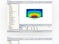
In this article, the design of a timber panel wall with the beam panel thickness type is performed.
.png?mw=512&hash=4a84cbc5b1eacf1afb4217e8e43c5cb50ed8d827)
This article provides a comprehensive overview of essential seismic analysis methods, explaining their principles and applications, as well as the scenarios in which they are most effective

Fire design according to Chapter 16 of the NDS [1] for wood members and surfaces is available in the Timber Design add-on. This article shows how the charring of wood and reduced cross-sectional dimensions can be accounted for in the fire design with an example from AWC Technical Report No. 10 [2].

When calculating regular structures, data input is often not complicated, but it is time-consuming. Save your valuable time with input automation. The task described in the present article is to consider the stories of a house as single construction stages. Data are entered using a C# program so that the user does not have to enter the elements of the individual floors manually.


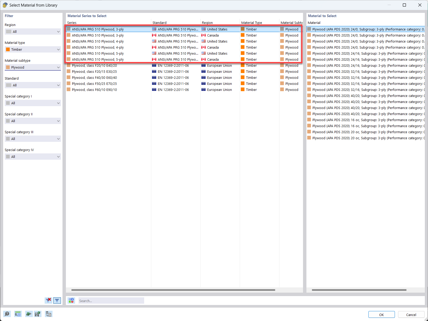
In the material library of RFEM, you can find plywood materials according to the US and Canadian standards ANSI/APA PRG 510 Plywood (USA/CAN).
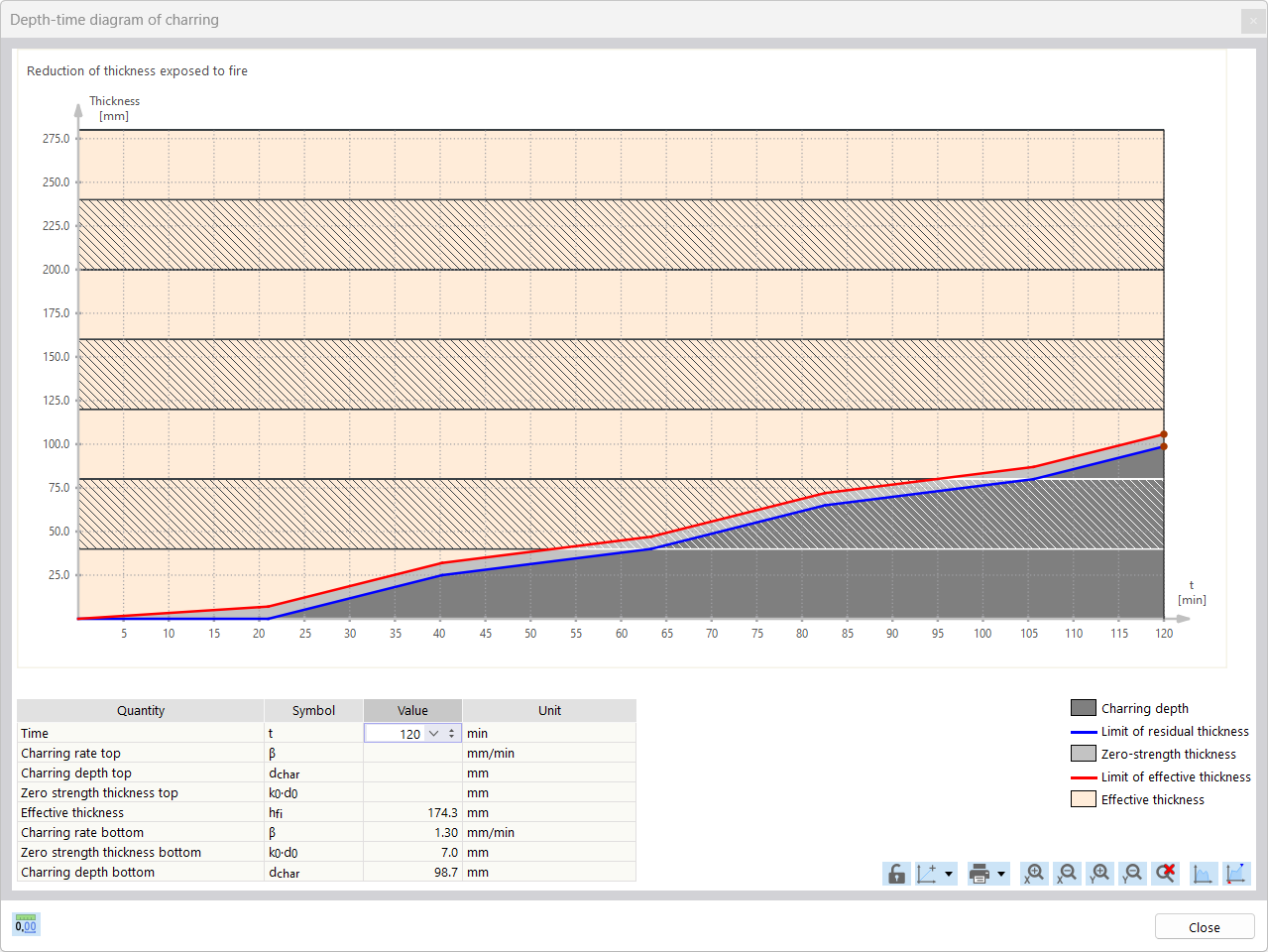
For the fire resistance design of timber surfaces, you can display a charring diagram depending on the time of fire exposure.
It is also possible to print this charring diagram into the printout report.
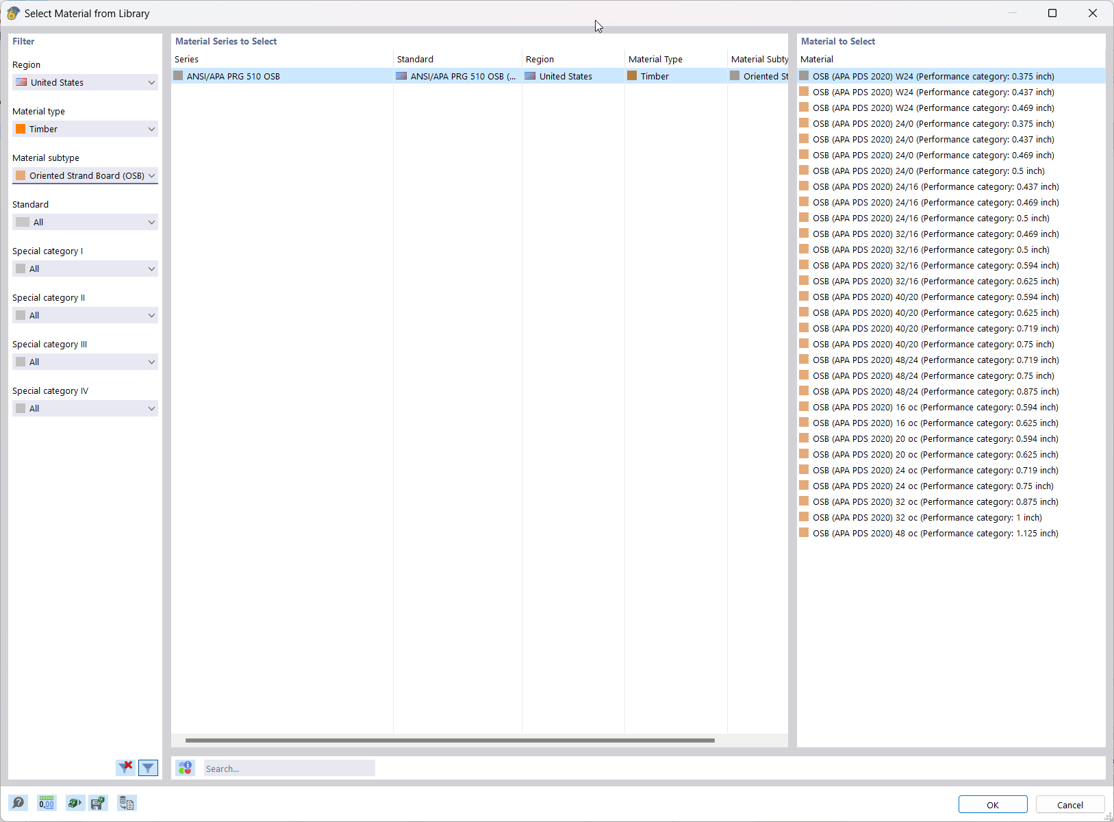
In RFEM, the oriented strand board (OSB) material is available for the USA and Canada. The material parameters are taken from the "Panel Design Specification manual".

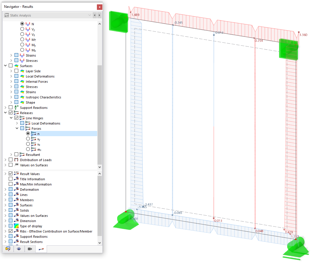
Using the "Beam Panel" thickness type, you can model timber panel elements in 3D space. Simply specify the surface geometry and the timber panel elements are automatically generated using an internal member-surface construct, including the element connection stiffness. The Beam Panel thickness type is defined using the Multilayer Surfaces add-on.
A "beam panel" provides you with the following advantages:
- Single-sided or double-sided sheathing
- Automatic calculation of a semi-rigid coupling between studs and sheathing
- Nailed sheathing connection
- Stapled sheathing connection
- User-defined sheathing connection
- Representation as a complete geometric 3D object (frame, studs, surface, etc.), including eccentricity and automatically calculated stiffness between elements
- Consider openings via surface cells
- Design of the individual structural elements utilizing the Timber Design add-on (full shear wall design planned for a future release)
- Other material options available (e.g., particle board, gypsum, or fiberboard sheathing with cold-formed steel sections)
Can I use RFEM to calculate a log house three-dimensionally?
Do I need to add a line hinge/line release for the CLT wall-to-floor connection in the Building Model add-on?
How can I add counteracting dead loads (0.9*D) in NBC load combinations?
How can I perform member design by case for different settings in the design configuration?
How can I exclude the dead load in NBC load combinations when performing a deflection check?
What is the conservatism factor for CLT in Timber Design?


