Would you like to mesh solids? Here you have the option of arranging a layered FE mesh. This option allows you to perform a defined division of the solid with finite elements between two parallel surfaces. Try it now!
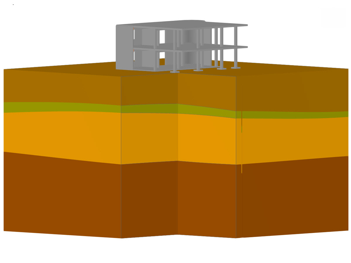
Layered Mesh for Solids
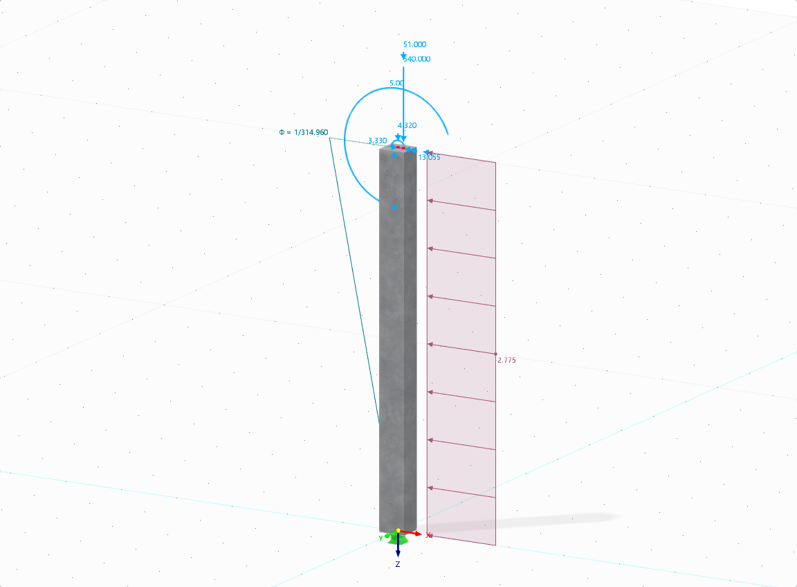
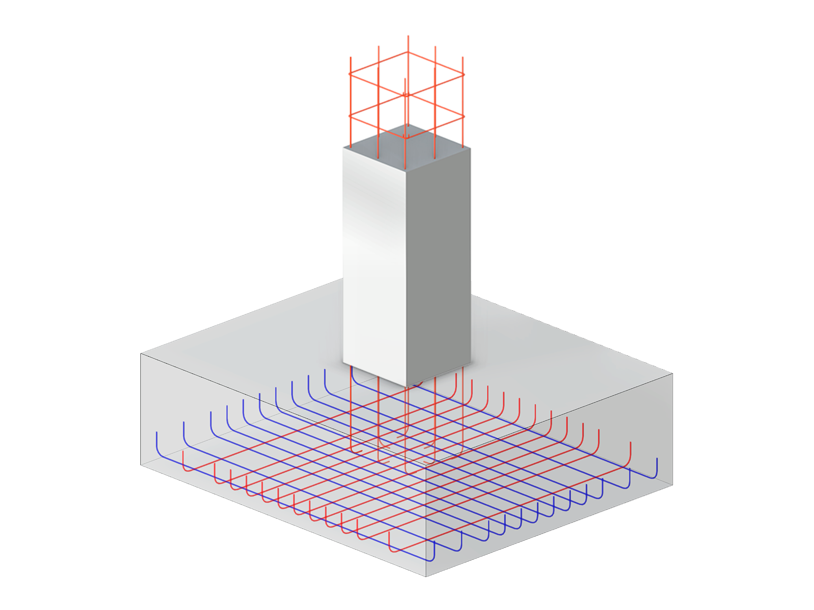
The aim of this technical article is to perform a design according to the general design method of Eurocode 2, using the example of a slender reinforced concrete column.

.png?mw=512&hash=4a84cbc5b1eacf1afb4217e8e43c5cb50ed8d827)

- Import of cross-sections, materials, and loads from RFEM
- Input of straight and parabolic tendons, layout definition of prestressing steel
- Automatic calculation of prestressing forces and equivalent member loads
- Transfer of equivalent loads to RFEM
- Consideration of short-term losses resulting due to friction, anchorage slippage, relaxation, elastic deformation of concrete, and so on
- Results of tendon strains before and after anchorage
- Calculation of the minimum and maximum stresses in tendons
- Internal forces results in defined sections
- Optional calculation of RF-TENDON Design in background
- Clear representation of tendon layout in 3D rendering
- Printout or RTF export of results
- Settings of display parameters and units (metric or imperial, decimal places etc.)
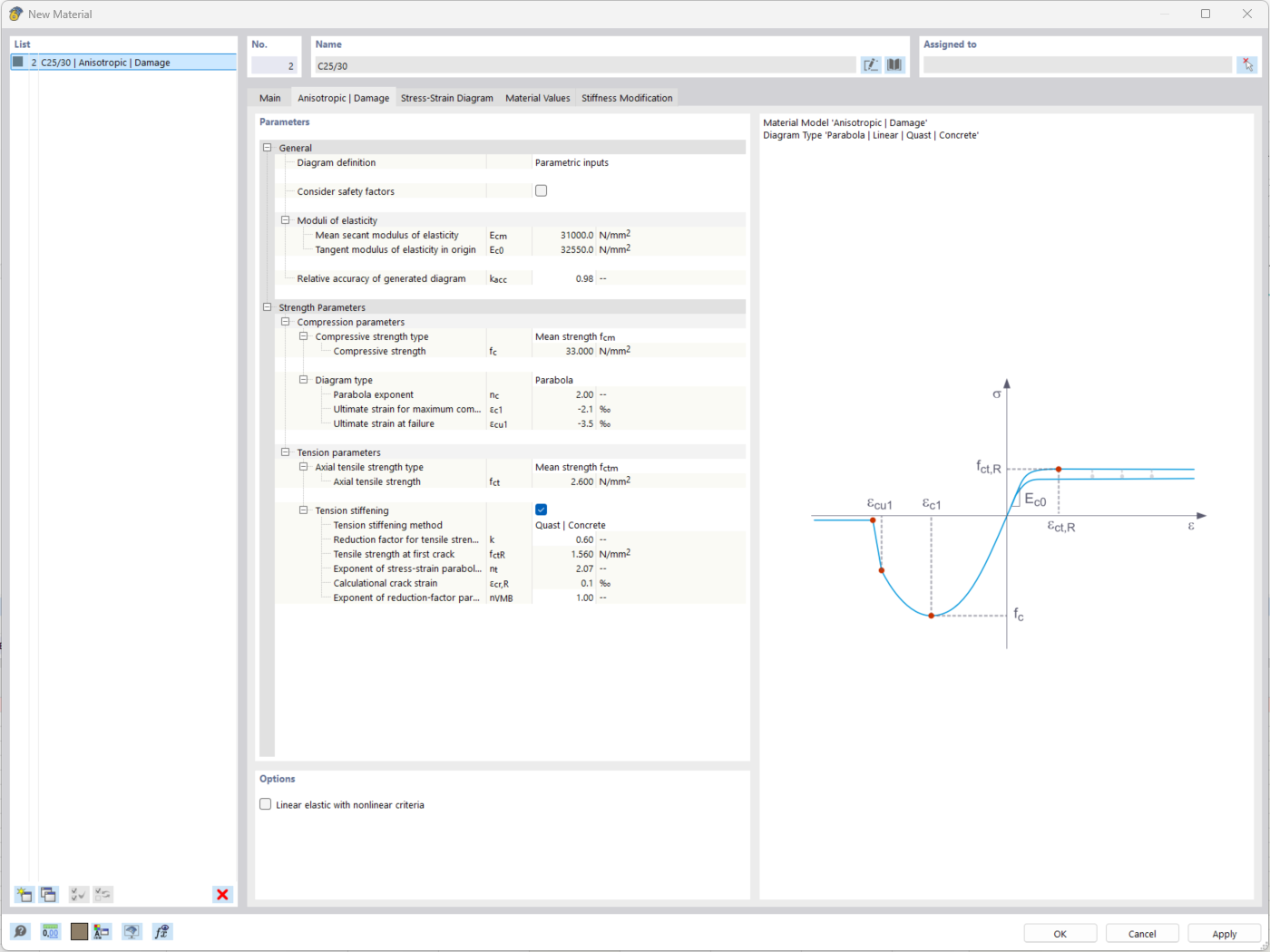
The "Nonlinear Material Behavior" add-on includes the Anistropic | Damage material model for concrete structural components. This material model allows you to consider concrete damage for members, surfaces, and solids.
You can define an individual stress-strain diagram via a table, use the parametric input to generate the stress-strain diagram, or use the predefined parameters from the standards. Furthermore, it is possible to consider the tension stiffening effect.
For the reinforcement, both nonlinear material models "Isotropic | Plastic (Members)" and "Isotropic | Nonlinear Elastic (Members)" are available.
It is possible to consider the long-term effects due to creep and shrinkage using the "Static Analysis | Creep & Shrinkage (Linear)" analysis type that has been recently released. Creep is taken into account by stretching the stress-strain diagram of the concrete using the factor (1+phi), and shrinkage is taken into account as the pre-strain of the concrete. More detailed time step analyses are possible using the "Time-Dependent Analysis (TDA)" add-on.
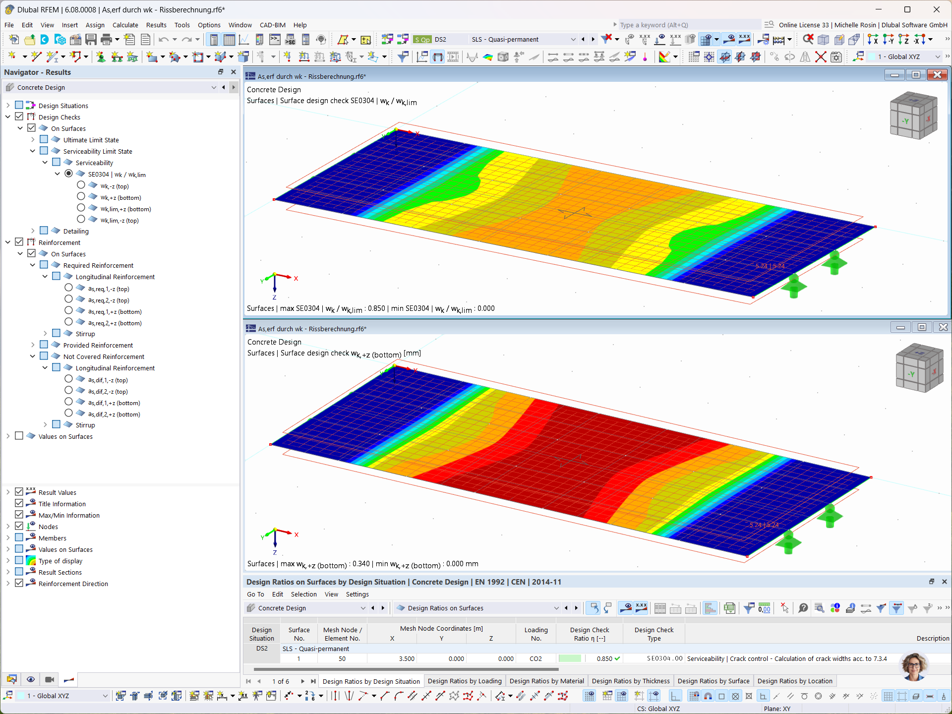
In the Concrete Design add-on, you can determine the required longitudinal reinforcement for the direct crack width analysis (w k).

For the design of reinforced concrete members, there is the option to automatically determine the number or diameter of rebars.
How can I check the determination of the required reinforcement?


Dlubal_KohlA_]_LI.jpg?mw=350&hash=d43473ab01992859ccffbb1254b61a07610a2a25)


_1.jpg?mw=350&hash=ab2086621f4e50c8c8fb8f3c211a22bc246e0552)


-querkraft-hertha-hurnaus.jpg?mw=350&hash=3306957537863c7a7dc17160e2ced5806b35a7fb)







.png?mw=600&hash=49b6a289915d28aa461360f7308b092631b1446e)


