- Stability analyses for flexural buckling, torsional buckling, and flexural-torsional buckling under compression
- Lateral-torsional buckling analysis of the structural components subjected to moment loading
- Import of the effective lengths from the calculation using the Structure Stability add-on
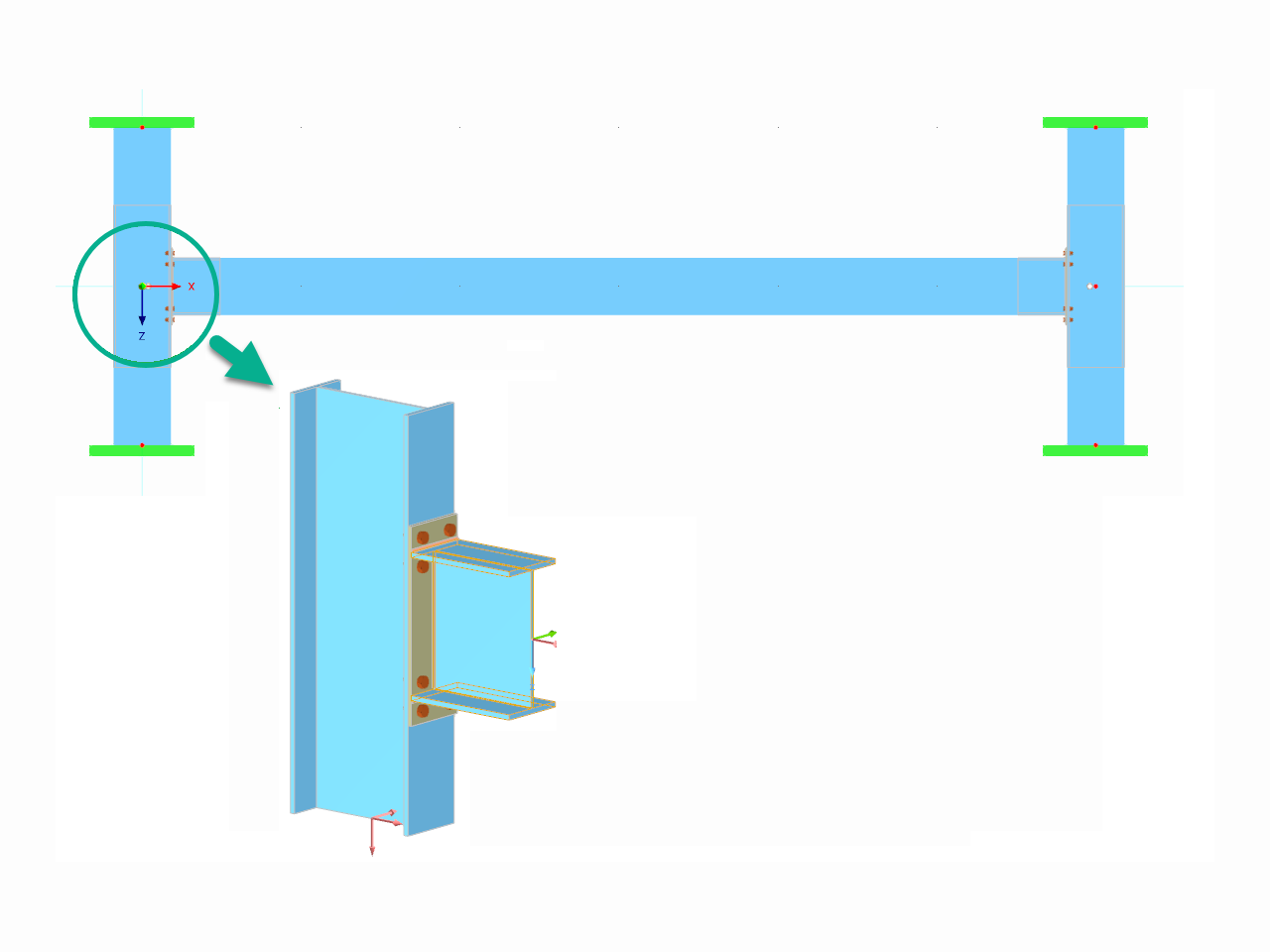
- Graphical input and check of the defined nodal supports and effective lengths for stability analysis
- Depending on the standard, a choice between user-defined input of Mcr, analytical method from the standard, or use of internal eigenvalue solver
- Consideration of a shear panel and a rotational restraint when using the eigenvalue solver
- Graphical display of a mode shape if the eigenvalue solver was used
- Stability analysis of structural components with the combined compression and bending stress, depending on the design standard
- Comprehensible calculation of all necessary coefficients, such as interaction factors
- Alternative consideration of all effects for the stability analysis when determining internal forces in RFEM/RSTAB (second-order analysis, imperfections, stiffness reduction, possibly in combination with the Torsional Warping (7 DOF) add-on)
Aluminum Design | Strength and Stability | Stability Analysis

Links


Duration: 01:10:25 min

Duration: 00:49:22 min
.png?mw=350&hash=c6c25b135ffd26af9cd48d77813d2ba5853f936c)
Duration: 00:02:51 min

Duration: 00:00:46 min

Duration: 00:00:59 min

Duration: 00:00:56 min

Duration: 00:53:57 min

Duration: 01:05:10 min

Duration: 01:24:40 min


This article explores the importance of considering joint-structure interaction in modeling and design and how to do it in RFEM 6.
.png?mw=512&hash=4a84cbc5b1eacf1afb4217e8e43c5cb50ed8d827)
This article provides a comprehensive overview of essential seismic analysis methods, explaining their principles and applications, as well as the scenarios in which they are most effective

The weld stresses between surfaces can be determined using the Stress-Strain Analysis add-on in RFEM 6. Furthermore, the stress limit determined according to the applicable standard can be input to determine the stress ratio of the weld. This article focuses on the fillet weld design according to AISC 360-22 [1] with two examples from AISC Volume 1: Design Examples [2].
This article demonstrates how to initiate and conduct the analysis in the software, followed by a short discussion of the underlying concept.


Want to automatically consider steel joint stiffness in your global RFEM model? Utilize the Steel Joints add-on!
Activate joint-structure interaction in the stiffness analysis of your steel joints. Hinges with springs are then automatically generated in the global model and included in subsequent calculations.

In the ultimate configuration of the steel joint design, you have the option to modify the limit plastic strain for welds.

The "Base Plate" component allows you to design base plate connections with cast-in anchors. In this case, plates, welds, anchorages, and steel-concrete interaction are analyzed.

In the "Edit Section" dialog box, you can display the buckling shapes of the Finite Strip Method (FSM) as a 3D graphic.
In the Steel Joints add-on, I get high utilization ratios for preloaded bolts in the tension design. Where do these high utilization ratios come from and how can I evaluate the load-bearing reserves of the bolt?
How can treating a connection as fully rigid result in an uneconomical design?
Is it possible to consider shear panels and rotational restraints in the global calculation?
A steel joint in my model is non-designable. How can I get more information to find the cause?
I am calculating a support that is clamped at the base, held in the X direction at the head, and can buckle in the Y direction. I have set the bar shear lengths using node carriers. In the verification, the buckling length values for the calculation are the same, L_(cr,z) = L_(cr,y) = 2.41 m. What am I doing wrong?
What is the Function of Chained Analysis Diagram?


_1.jpg?mw=350&hash=ab2086621f4e50c8c8fb8f3c211a22bc246e0552)


