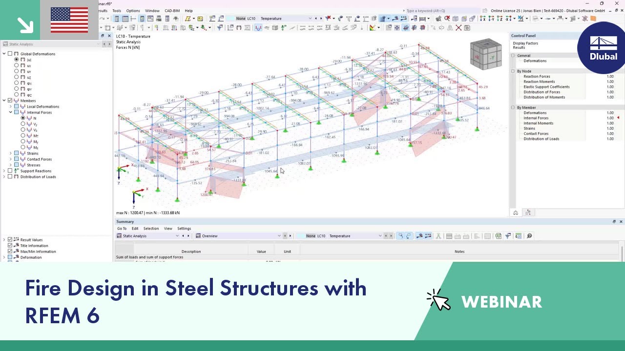
In most cases, the default setting "Shifted member ends/set of member ends" is suitable for considering the displacements of the total structural system in the design. For the beam shown in the figure, however, the reference length has been changed manually to the span between the supports. In this case, the deformation must be related to the undeformed system in order for the correct deflection to be integrated in the design.
Relation of Deformations
Not only do RF-/STEEL EC3 and RF-/TIMBER Pro perform cross-section designs and stability analyses, they allow you to perform serviceability limit state designs. For this, it is possible to relate the deformation to the undeformed initial system or to shifted members ends.
Author
Mr. Vogl creates and maintains the technical documentation.
Links


Duration: 01:10:25 min

Duration: 00:49:22 min
.png?mw=350&hash=c6c25b135ffd26af9cd48d77813d2ba5853f936c)
Duration: 00:02:51 min

Duration: 00:44:46 min

Duration: 00:00:23 min

Duration: 00:00:29 min

Duration: 00:00:46 min

Duration: 01:03:34 min

Duration: 00:00:59 min


This article explores the importance of considering joint-structure interaction in modeling and design and how to do it in RFEM 6.
In this article, the design of a timber panel wall with the beam panel thickness type is performed.
.png?mw=512&hash=4a84cbc5b1eacf1afb4217e8e43c5cb50ed8d827)
This article provides a comprehensive overview of essential seismic analysis methods, explaining their principles and applications, as well as the scenarios in which they are most effective

The weld stresses between surfaces can be determined using the Stress-Strain Analysis add-on in RFEM 6. Furthermore, the stress limit determined according to the applicable standard can be input to determine the stress ratio of the weld. This article focuses on the fillet weld design according to AISC 360-22 [1] with two examples from AISC Volume 1: Design Examples [2].


Want to automatically consider steel joint stiffness in your global RFEM model? Utilize the Steel Joints add-on!
Activate joint-structure interaction in the stiffness analysis of your steel joints. Hinges with springs are then automatically generated in the global model and included in subsequent calculations.
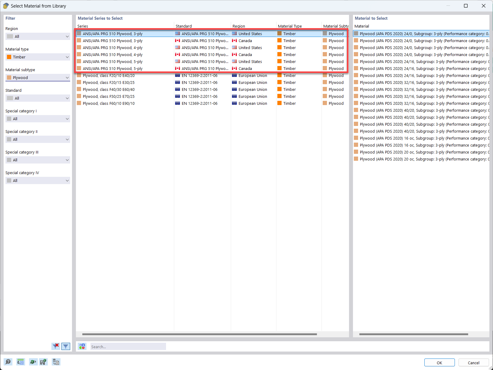
In the material library of RFEM, you can find plywood materials according to the US and Canadian standards ANSI/APA PRG 510 Plywood (USA/CAN).
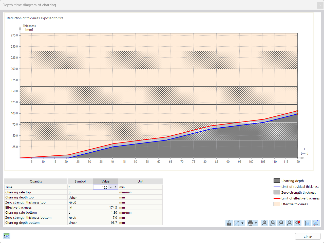
For the fire resistance design of timber surfaces, you can display a charring diagram depending on the time of fire exposure.
It is also possible to print this charring diagram into the printout report.
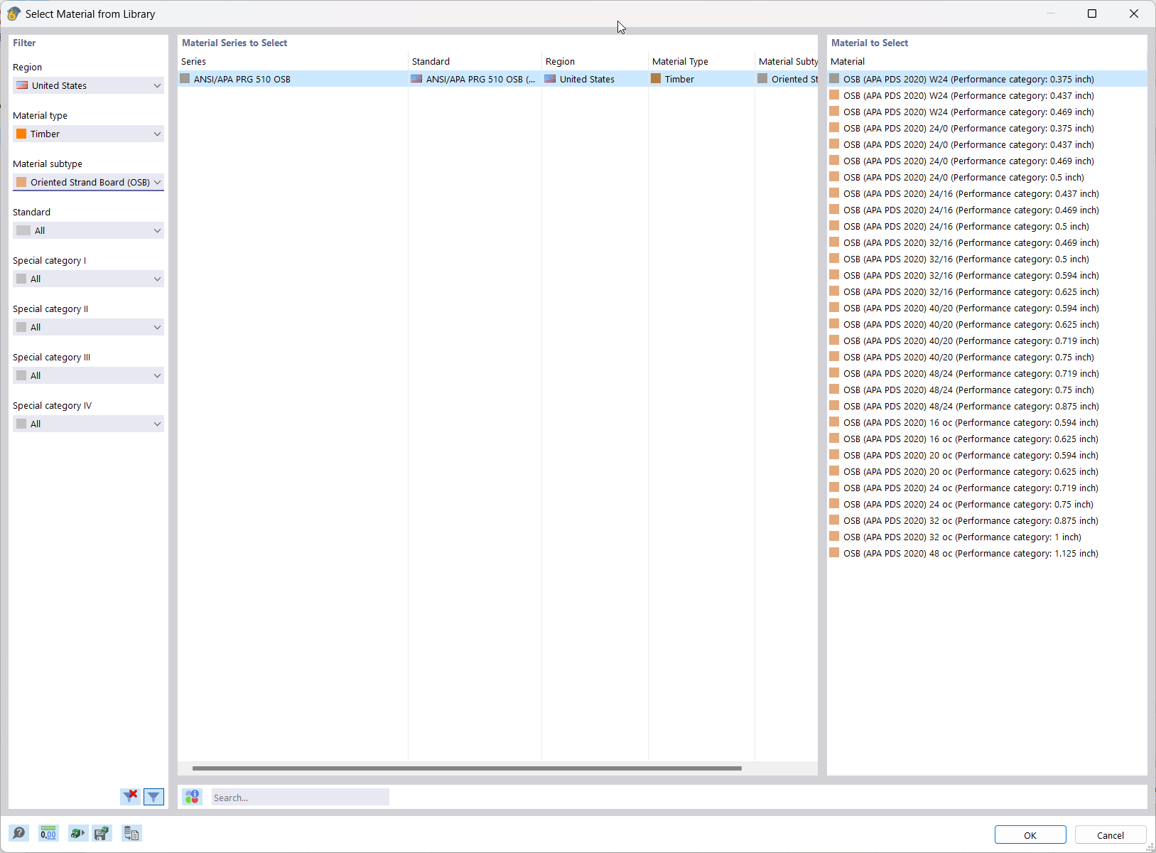
In RFEM, the oriented strand board (OSB) material is available for the USA and Canada. The material parameters are taken from the "Panel Design Specification manual".
Why do the results of members and sets of members differ in the design?
In the case of the serviceability limit state design (for example, of a steel beam), the precamber is not taken into account. Is this a program error or is my entry incorrect?
In the Steel Joints add-on, I get high utilization ratios for preloaded bolts in the tension design. Where do these high utilization ratios come from and how can I evaluate the load-bearing reserves of the bolt?
How can treating a connection as fully rigid result in an uneconomical design?
Is it possible to consider shear panels and rotational restraints in the global calculation?
Do I need to add a line hinge/line release for the CLT wall-to-floor connection in the Building Model add-on?


_1.jpg?mw=350&hash=ab2086621f4e50c8c8fb8f3c211a22bc246e0552)


