How may I help you?
Do you have any questions about Dlubal products or need assistance in selecting the right one for your project?
I'm here to help. You can easily reach me through the contact options provided below.
Looking forward to hearing from you!
Amy Heilig, PE
CEO – USA Subsidiary | Sales Engineer


Design of Timber Members According to SANS 10163‑1:2003 and SANS 10163‑2:2001
Total items: 4

Graphical Representation of RF-/TIMBER SANS Design Results in RFEM | Features
- Full integration in RFEM/RSTAB including import of all relevant information and internal forces
- Design of members and continuous members for tension, compression, bending, shear, and combined internal forces
- Stability analysis for lateral-torsional buckling and buckling according to the equivalent member method or the second order analysis
- Serviceability limit state design by limitation of deflections
- Free configuration of charring time and charring rates, as well as free choice of charring sides for fire design
- South African material library and cross‑section library
- User-defined entry of rectangular and circular cross-sections
- Cross-section optimization with optional transfer to RFEM/RSTAB
- Optional import of effective lengths from the RSBUCK or RF‑STABILITY add‑on module
- Detailed result documentation including references to design equations of the used standard
- Various filter and sorting options of results including result lists by member, cross-sections, x-location, or by load case, load and result combination
- Consideration of moisture service conditions
- Visualization of the design criterion on the RFEM/RSTAB model
- Data export to MS Excel

Graphical Representation of RF-/TIMBER SANS Design Results in RFEM | Input
After opening the add‑on module, it is necessary to select the members/sets of members, load cases, load or result combinations for the ultimate limit state, serviceability limit state, and fire resistance design. The materials from RFEM/RSTAB are preset and can be adjusted in RF‑/TIMBER SANS. Material properties listed in the respective standard are included in the material library.
When checking the cross-sections, you can specify whether to consider a cross-section selected in RFEM/RSTAB, or a modified cross-section. Then, you can define the load duration classes, the moisture service conditions, and timber treatment.
The deformation analysis requires the reference lengths of the relevant members and sets of members. Furthermore, you can define a specific direction of deflection, precamber and the beam type.
For fire resistance design, you can define the charring sides of a member or set of members.

Graphical Representation of RF-/TIMBER SANS Design Results in RFEM | Design
The cross-section resistance design analyzes tension and compression along the grain, bending, bending and tension/compression as well as the strength in shear due to shear force.
The design of structural components at risk of buckling or lateral buckling is performed according to the Equivalent Member Method and considers the systematic axial compression, bending with and without compression force as well as bending and tension. Deflection of inner spans and cantilevers is compared with the maximum allowable deflection.
Separate design cases allow a flexible analysis for selected members, sets of members, and actions, as well as for the individual stability analyses. such as stability analysis, load duration in case of fire, member slendernesses, and limit deflection can be adjusted as desired.

Graphical Representation of RF-/TIMBER SANS Design Results in RFEM | Results
After the calculation, the module displays results in clearly arranged result tables. All intermediate values (for example, governing internal forces, adjustment factors, and so on) can be included in order to make the design more transparent. The results are listed by load case, cross-section, member, and set of members.
If the analysis fails, the relevant cross-sections can be modified in an optimization process. It is also possible to transfer the optimized cross-sections to RFEM/RSTAB to perform a new calculation.
The design ratio is represented with different colors in the RFEM/RSTAB model. This way, you can quickly recognize critical or oversized areas of the cross-section. Furthermore, result diagrams displayed on the member or set of members ensure targeted evaluation.
In addition to the input and result data, including design details displayed in tables, you can add all graphics into the printout report. This way, comprehensible and clearly arranged documentation is guaranteed. You can select the report contents and extent specifically for the individual designs.
.png?mw=192&hash=f63e4a3f1836233005de32f60201d5392e507cf1)
Webshop
Customize your individual program package and find out all the prices online!
Calculate Your Price

Total Amount 2,170.00 USD
The price is valid for United States.


Implemented Standards for Reinforced Concrete Design
Standards for Concrete Design
Annexes for EN 1992-1-1


Duration: 01:05:10 min

Duration: 00:43:11 min

Duration: 01:03:11 min
Duration: 00:01:11 min

Duration: 01:12:48 min

Duration: 01:04:33 min

Duration: 01:15:40 min

Duration: 00:59:06 min

Duration: 01:08:55 min


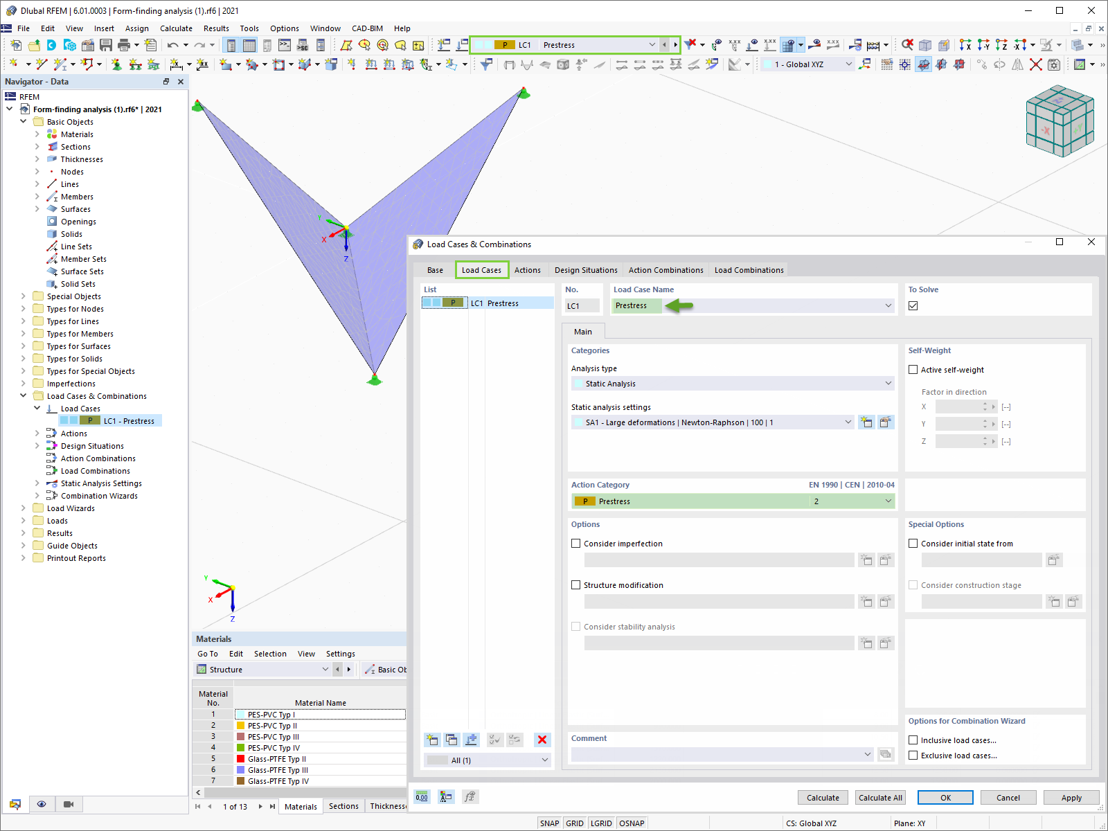
RFEM 6 includes the Form-Finding add-on to determine the equilibrium shapes of surface models subjected to tension and members subjected to axial forces. Activate this add-on in the model's Base Data and use it to find the geometric position in which the prestress of lightweight structures is in equilibrium with the existing boundary conditions.

This article provides an overview of the Dlubal-Tekla interface, detailing the export and import options, as well as the various workflows for efficiently managing data exchange between Tekla Structures and RFEM 6 in structural design and analysis.

This article explains how to simulate the thermal strain of structural components in RFEM 6 using temperature loads, covering both membrane and bending effects, with practical examples to demonstrate their application.

This article provides a detailed overview of the export features from RFEM 6 and RSTAB 9 to AutoCAD/DXF files, including options for exporting dimensions, FE meshes, and deformed shapes.


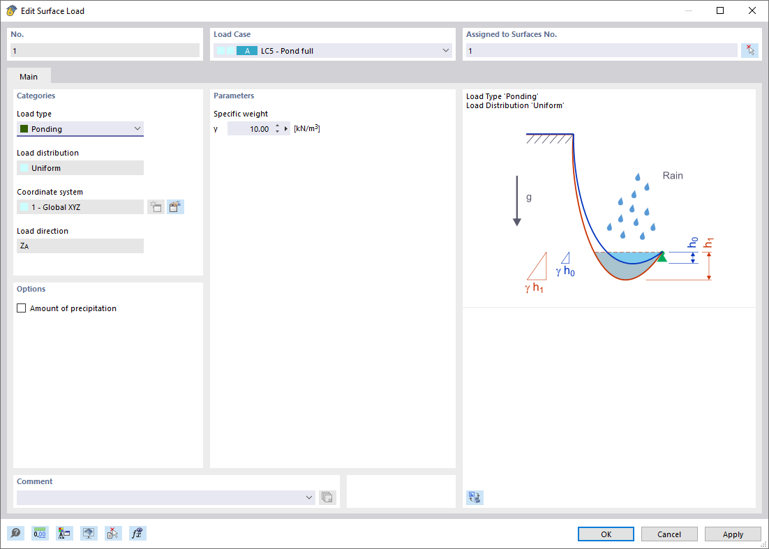
The Ponding load type allows you to simulate rain actions on multi-curved surfaces, taking into account the displacements according to the large deformation analysis.
This numerical rainfall process examines the assigned surface geometry and determines which rainfall portions drain away and which rainfall portions accumulate in puddles (water pockets) on the surface. The puddle size then results in a corresponding vertical load for the structural analysis.
For example, you can use this feature in the analysis of approximately horizontal membrane roof geometries subjected to rain loading.
Go to Explanatory Video
In the Snow Load Wizard, you can optionally consider snow overhang and snow guard when generating snow loads according to Eurocode.

The Construction Stages Analysis (CSA) add-on allows you to modify the object and design properties of members, surfaces, and so on, in the individual construction stages.

During the calculation, you can display the model deformation for the calculation steps graphically in the calculation progress window.
How can I export the deformed mesh shape to a .dxf file in RFEM 6 for my fabric membrane structure?
I would like to analyze temporary structures. Which programs do you recommend?
Which Dlubal programs do I need for tensile membrane structures?
I would like to analyze cable and tensile structures. Is it possible to use RFEM or RSTAB for this?
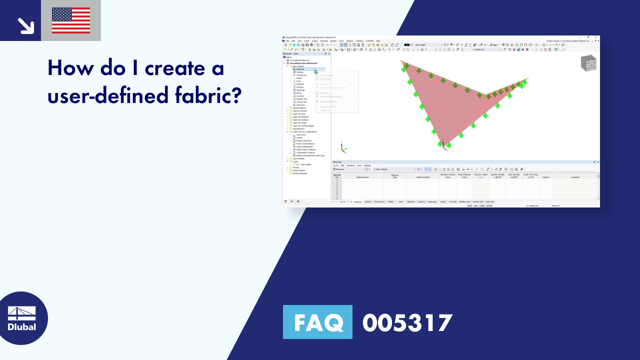
How do I create a user-defined fabric?
Is it possible also to design membrane structures in RFEM?


-querkraft-hertha-hurnaus.jpg?mw=350&hash=3306957537863c7a7dc17160e2ced5806b35a7fb)