Description
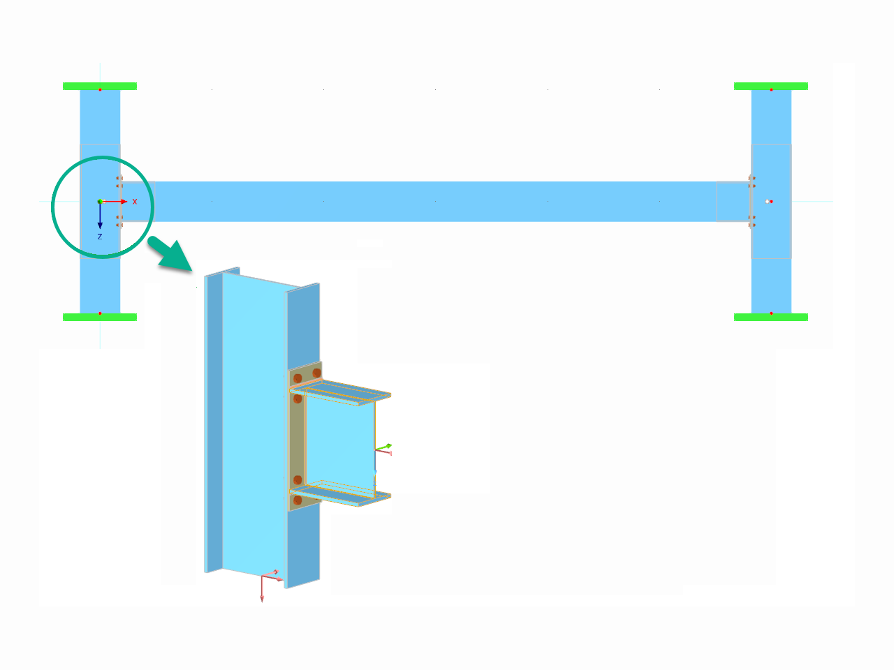
A structure consists of I-profile simply supported beam. The axial rotation φx is restricted on the both ends but the cross-section is free to warp (fork support). The beam has an initial imperfection in Y-direction defined as a parabolic curve with maximum displacement 30 mm in the middle. Uniform loading is applied in the middle of the top flange of I-profile. The problem is described by the following set of parameters. The verification example is based on the example introduced by Gensichen and Lumpe see the reference.
| Material | Steel S235 | Modulus of Elasticity | E | 210000.000 | MPa |
| Shear Modulus | G | 81000.000 | MPa | ||
| Geometry | Structure | Length | L | 6.000 | m |
| Imperfection | Maximum Imperfection | imax | 30.000 | mm | |
| I-profile | Height | h | 400.000 | mm | |
| Width | b | 180.000 | mm | ||
| Web Thickness | s | 10.000 | mm | ||
| Flange Thickness | t1 | 14.000 | mm | ||
| Load | Continuous Load | q | 30.000 | kN/m | |
| Eccentricity | ez | -200.000 | mm | ||

Analytical Solution
Analytical solution is not available. Results from software S3D are taken as reference.
RFEM and RSTAB Settings
- Modeled in RFEM 6.06 and RSTAB 9.06
- The element size is lFE= 0.010 m
- Isotropic linear elastic material model is used
- The number of increments is 10
- Second-Order and Large Deformation Analysis are used
- Torsional Warping (7DOF) Add-on is used
- The problem is modeled both by members and a combination of members and surface elements
- Stiffness is reduced by means of Partial Safety Factor γM=1.1
Results
Two modeling techniques are used in RFEM 6. At first, the I-section is modeled as a beam with given imperfection (parabolic shape). Next, the I-profile is modeled by means of surface elements (plates). In this case the boundary conditions are modeled as close as possible to the beam case, but the results can be influenced by the differencies in the modeling style. In RSTAB 9 the imperfection is modeled by means of the set of short beams with given imperfection in nodes.
RSTAB 9 results:
| Quantity | S3D | RSTAB 9 - Second-Order Analysys | Ratio | RSTAB 9 - Large Deformation Analysys | Ratio |
| uy(x=3 m) [mm] | 24.2 | 31.041 | 1.283 | 30.182 | 1.247 |
| uz(x=3 m) [mm] | 18.8 | 16.772 | 0.892 | 22.644 | 1.204 |
| φx(x=3 m) [mrad] | 152 | 186.528 | 1.227 | 194.596 | 1.280 |
| My(x=3 m) [kNm] | 134 | 134.738 | 1.006 | 135.550 | 1.012 |
| Mz(x=3 m) [kNm] | -20.5 | -24.875 | 1.213 | -26.716 | 1.303 |
| Mω(x=3 m) [kNm2] | 4.02 | 5.053 | 1.257 | 5.276 | 1.312 |
| MTpri(x=0 m) [kNm] | 2.91 | 3.165 | 1.088 | 3.301 | 1.134 |
| MTsec(x=3 m) [kNm] | 1.78 | 2.307 | 1.296 | 2.410 | 1.354 |
RFEM 6 results:
| Quantity | S3D | RFEM 6 - Second-Order Analysys | Ratio | RFEM 6 - Large Deformation Analysys | Ratio | RFEM 6 - Plates - Large Deformation Analysys | Ratio |
| uy(x=3 m) [mm] | 24.2 | 14.476 | 0.598 | 26.962 | 1.114 | 26.339 | 1.088 |
| uz(x=3 m) [mm] | 18.8 | 14.022 | 0.746 | 20.213 | 1.075 | 20.159 | 1.072 |
| φx(x=3 m) [mrad] | 152 | 86.937 | 0.572 | 175.234 | 1.153 | 172.512 | 1.135 |
| My(x=3 m) [kNm] | 134 | 133.477 | 0.996 | 132.992 | 0.992 | - | - |
| Mz(x=3 m) [kNm] | -20.5 | -17.476 | 0.852 | -23.546 | 1.149 | - | - |
| Mω(x=3 m) [kNm2] | 4.02 | 2.335 | 0.581 | 4.716 | 1.173 | - | - |
| MTpri(x=0 m) [kNm] | 2.91 | 1.490 | 0.512 | 3.002 | 1.032 | - | - |
| MTsec(x=3 m) [kNm] | 1.78 | 1.160 | 0.652 | 2.300 | 1.292 | - | - |


.png?mw=350&hash=c6c25b135ffd26af9cd48d77813d2ba5853f936c)


.png?mw=512&hash=4a84cbc5b1eacf1afb4217e8e43c5cb50ed8d827)


_1.jpg?mw=350&hash=ab2086621f4e50c8c8fb8f3c211a22bc246e0552)


