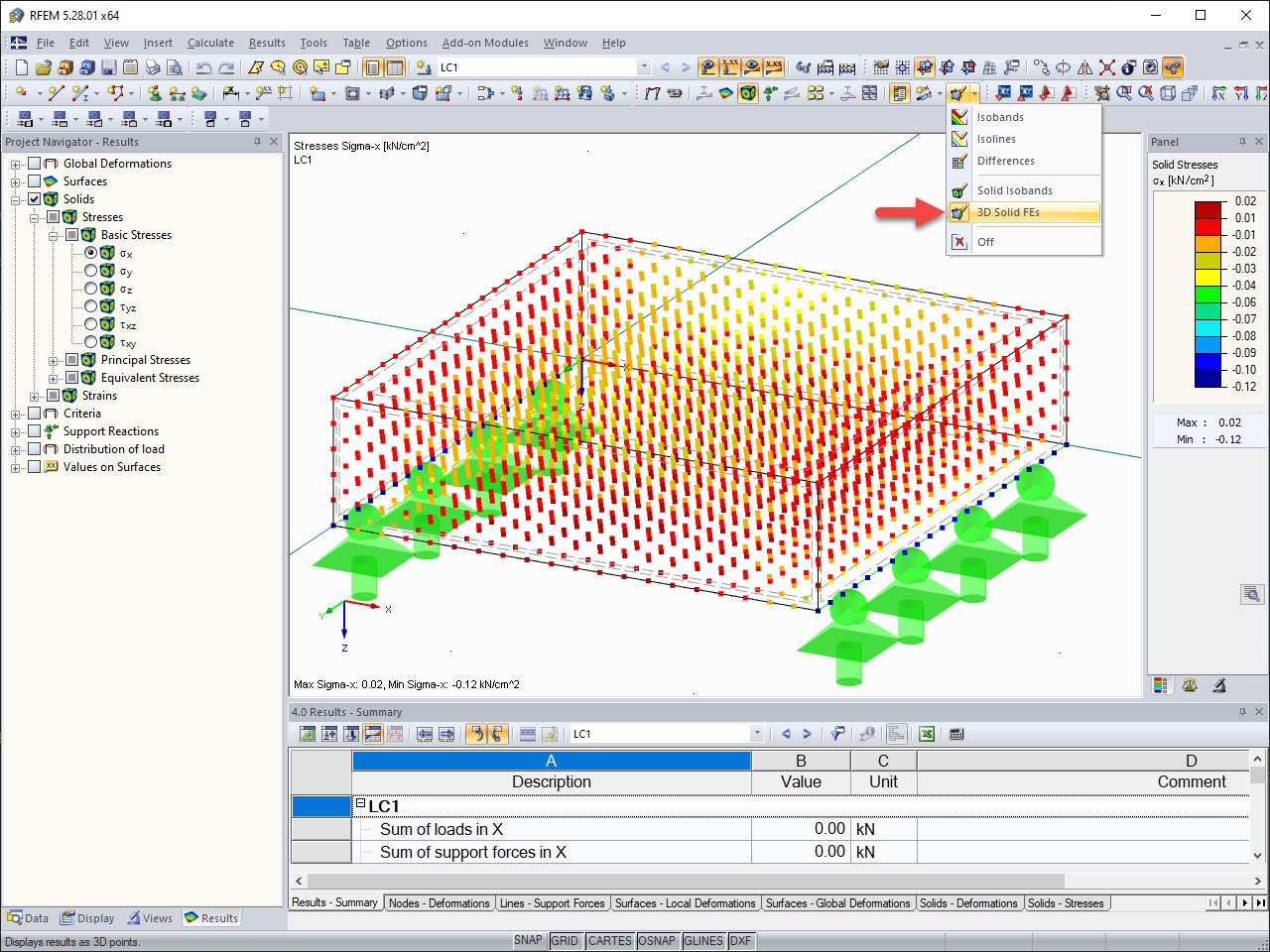
For a detailed display, it is useful to model a contact solid.
To do this, it is necessary first to divide the channel section into surfaces (right-click the member → Generate Surfaces from Member). Then, the web surface or the surface of the channel section to be welded must be projected into the steel surface:
- Copy nodes and lines into the plane.
- Divide the steel surface using integrated lines (right-click the member → Divide Surface).
- Define null surfaces as boundary surfaces of the contact solid.
Now you can create a contact solid between the two surfaces lying on top of each other (click "New Solid" → Contact Solid → select boundary surfaces); see Image 01.


.png?mw=350&hash=c6c25b135ffd26af9cd48d77813d2ba5853f936c)


![Basic Shapes of Membrane Structures [1]](/en/webimage/009595/2419502/01-en-png-png.png?mw=512&hash=6ca63b32e8ca5da057de21c4f204d41103e6fe20)


.png?mw=512&hash=ea9bf0ab53a4fb0da5c4ed81d32d53360ab2820c)


_1.jpg?mw=350&hash=ab2086621f4e50c8c8fb8f3c211a22bc246e0552)


