We have screwed around a bit with our add-ons and would like to draw your attention to a useful feature now. To determine the shear resistance of bolts, you can use the Steel Joints add-on to specify whether there is a shaft or a thread in the shear plane.
Shear Resistance of Bolts

The RF‑/STEEL EC3 add-on module can perform the design of fillet welds for all parametric, welded cross-sections of the cross-section library. For this, the option must be activated in the detail settings of the module. As an alternative, you can also use a surface model for the design.

In RF-STEEL Surfaces, it is possible to display the stresses relevant for the design of welds, for example, according to EN 1993‑1‑8, Figure 4.5. When evaluating the stress components, the local xyz-axis system of the surfaces must be considered.

A fillet weld is the most common weld type in steel building construction. According to EN 1993-1-8, 4.3.2.1 (1) [1], fillet welds may be used for connecting structural part where the fusion faces form an angle of between 60° and 120°.
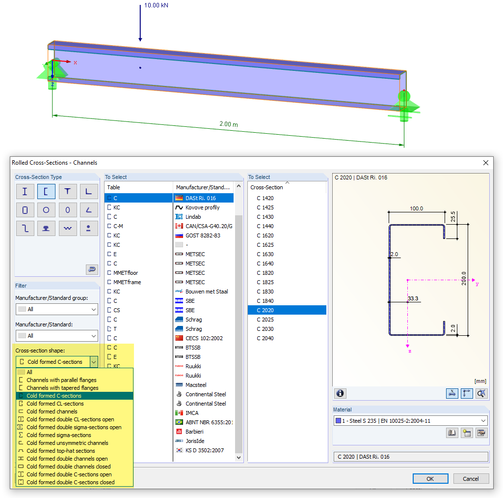
The design of cold-rolled steel products is defined in EN 1993-1-3. Typical cross-section shapes are channel, C, Z, top hat, and sigma sections. These are cold-rolled steel products made of thin-walled sheet metal that has been cold-formed by roll-forming or bending methods. When designing the ultimate limit states, it is also necessary to ensure that local transverse forces do not lead to compression, crippling of the web, or local buckling in the web of the sections. These effects can be caused by local transverse forces by the flange into the web, as well as by support forces at the supported points. Section 6.1.7 of EN 1993-1-3 specifies in detail how to determine the resistance of the web Rw,Rd under local transverse forces.
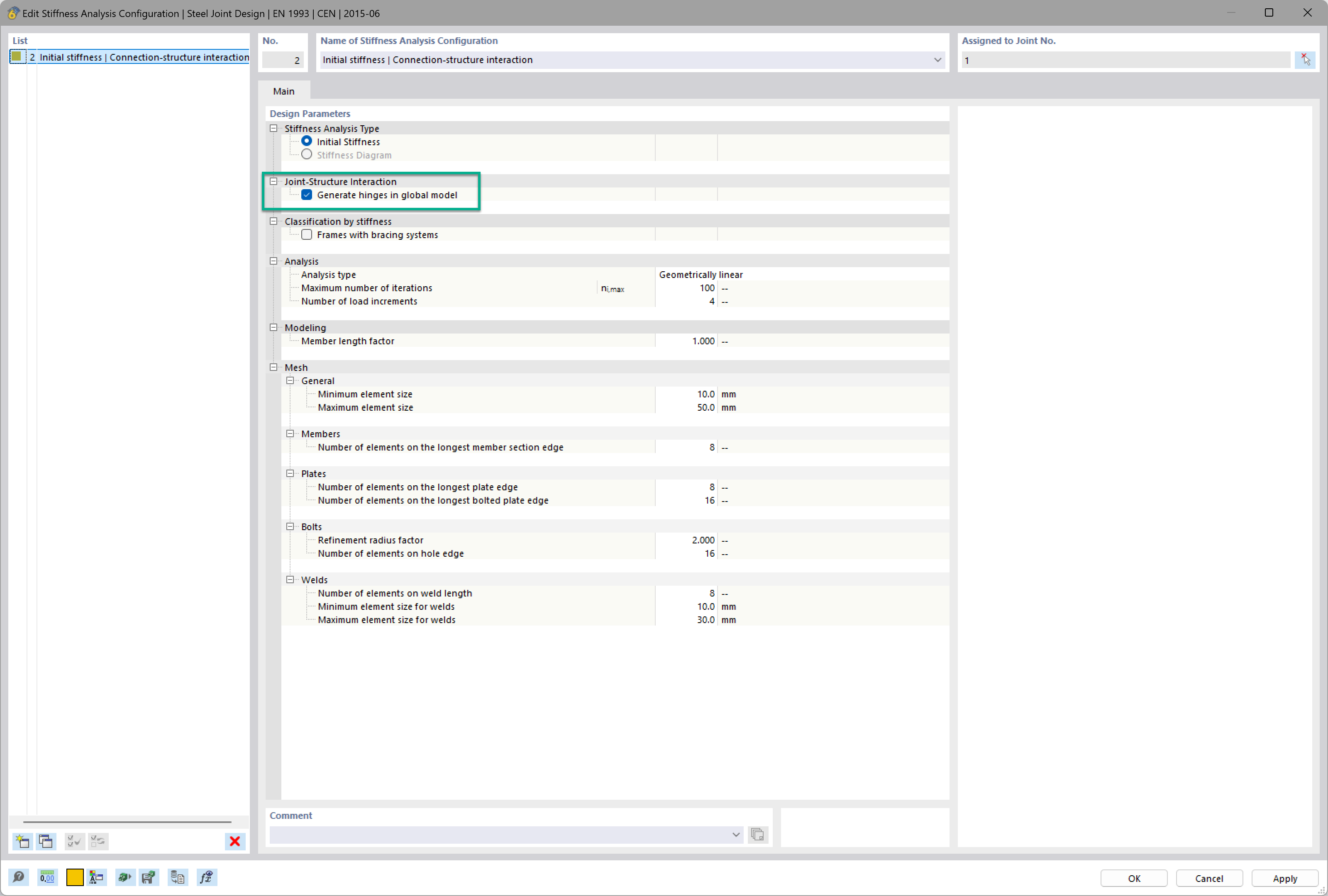
Want to automatically consider steel joint stiffness in your global RFEM model? Utilize the Steel Joints add-on!
Activate joint-structure interaction in the stiffness analysis of your steel joints. Hinges with springs are then automatically generated in the global model and included in subsequent calculations.
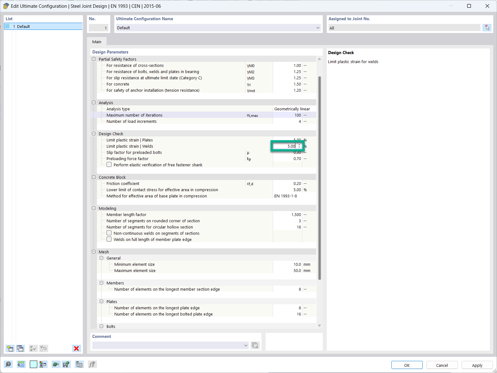
In the ultimate configuration of the steel joint design, you have the option to modify the limit plastic strain for welds.
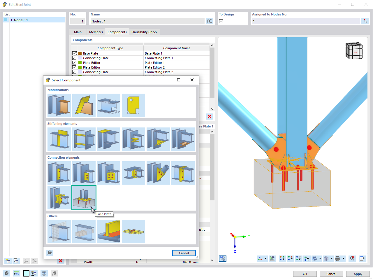
The "Base Plate" component allows you to design base plate connections with cast-in anchors. In this case, plates, welds, anchorages, and steel-concrete interaction are analyzed.
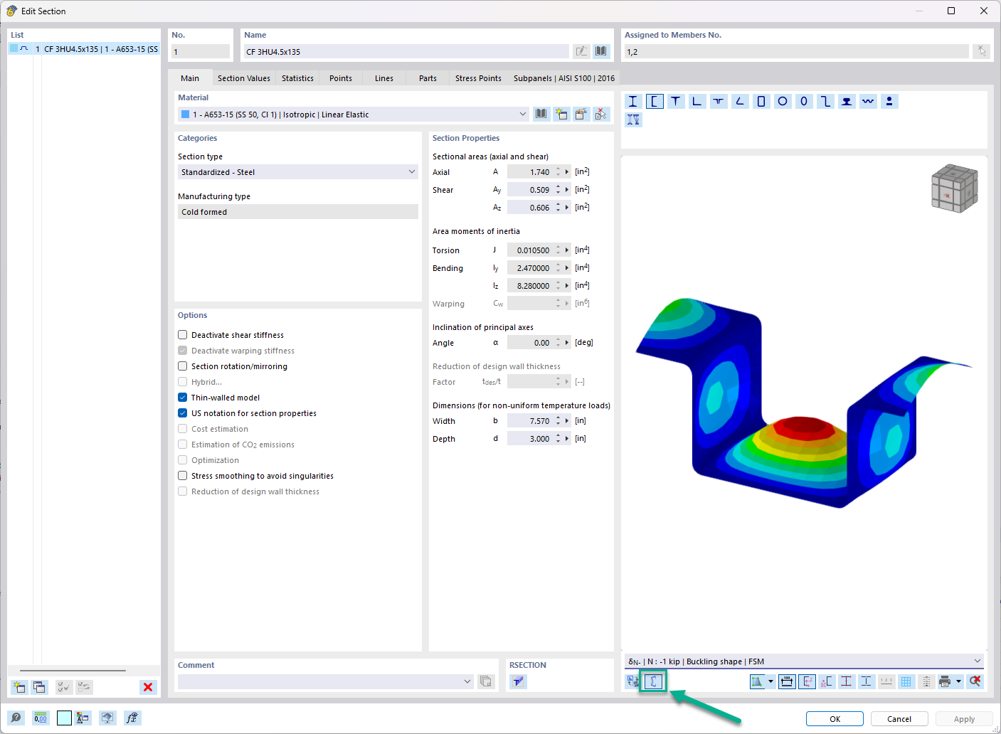
In the "Edit Section" dialog box, you can display the buckling shapes of the Finite Strip Method (FSM) as a 3D graphic.
What is the meaning of the "Activate Weld Design" option in the detailed settings of RF‑/STEEL EC3?
I am comparing the flexural buckling design according to the equivalent member method and the internal forces according to the linear static analysis with the stress calculation according to the second-order analysis, including imperfections. The differences are very large. What can be the reason for this?
I cannot see any members if the RF‑/STEEL EC3 add-on module is selected as a "load case"; why?
To which axes do the support rotations and support eccentricities in RF‑/STEEL EC3 Warping Torsion refer?
What does the load application point in RF-/STEEL EC3 Warping Torsion refer to?
When designing a beam, I would like to neglect the torsion included in the stability analyses using the filters described in Knowledge Base article #001498.
I define the filter, but the torsion warning appears at the same x‑location again. Do the design internal forces change, or why is that?
Recommended Products for You


.png?mw=350&hash=c6c25b135ffd26af9cd48d77813d2ba5853f936c)


_1.jpg?mw=350&hash=ab2086621f4e50c8c8fb8f3c211a22bc246e0552)


.png?mw=600&hash=49b6a289915d28aa461360f7308b092631b1446e)


