Modeling Downstand Beam in Timber Structures 3: Nonlinear Support Situation
In order to increase the stiffness of a ceiling structure in case of renovation, visible downstand beams are used that are not connected to the ceiling structure. Nonlinear line releases can be used to transfer only the compression forces. If there are tensile forces between the ceiling and the downstand beam, as shown in the figure, the downstand beam does not transfer the stiffness in the overall structure.

Author
Mr. Rehm is responsible for developing products for timber structures, and he provides technical support for customers.
Links
- Modeling Downstand Beam in Timber Structures 1: Torsion
- Modeling Downstand Beam in Timber Structures 2: Shear Coupling
- Modeling Downstand Beam in Timber Structures 3: Nonlinear Support Situation
- Useful Tools for Fast Generation of Structures in RFEM


Duration: 00:00:40 min

Duration: 00:00:30 min

Duration: 00:00:41 min
Duration: 00:00:33 min

Duration: 00:00:57 min

Duration: 00:00:51 min
Duration: 00:01:00 min

Duration: 01:14:03 min

Duration: 00:00:56 min


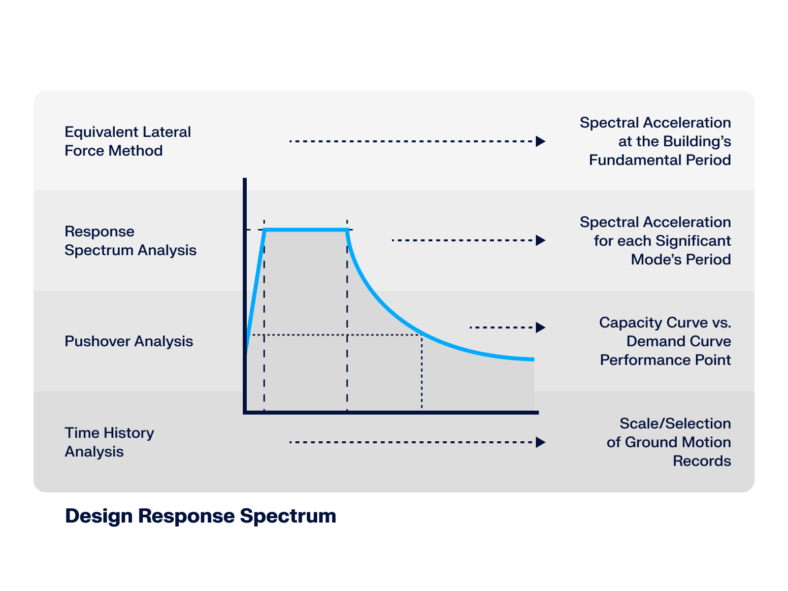
This article* explores the role of the Design Response Spectrum across different seismic analysis methods, demonstrating its significance from simplified static approaches up to advanced dynamic simulations.
.png?mw=512&hash=71474bbf484eff50cf2eb4da2f7c0a5d6103a65d)
This article provides an overview of RFEM 6 and RSTAB 9's dynamic analysis capabilities, highlighting essential add-ons and learning resources for seismic analysis, vibration-resistant design, and structural dynamics applications.
.png?mw=512&hash=4a84cbc5b1eacf1afb4217e8e43c5cb50ed8d827)
This article provides a comprehensive overview of essential seismic analysis methods, explaining their principles and applications, as well as the scenarios in which they are most effective

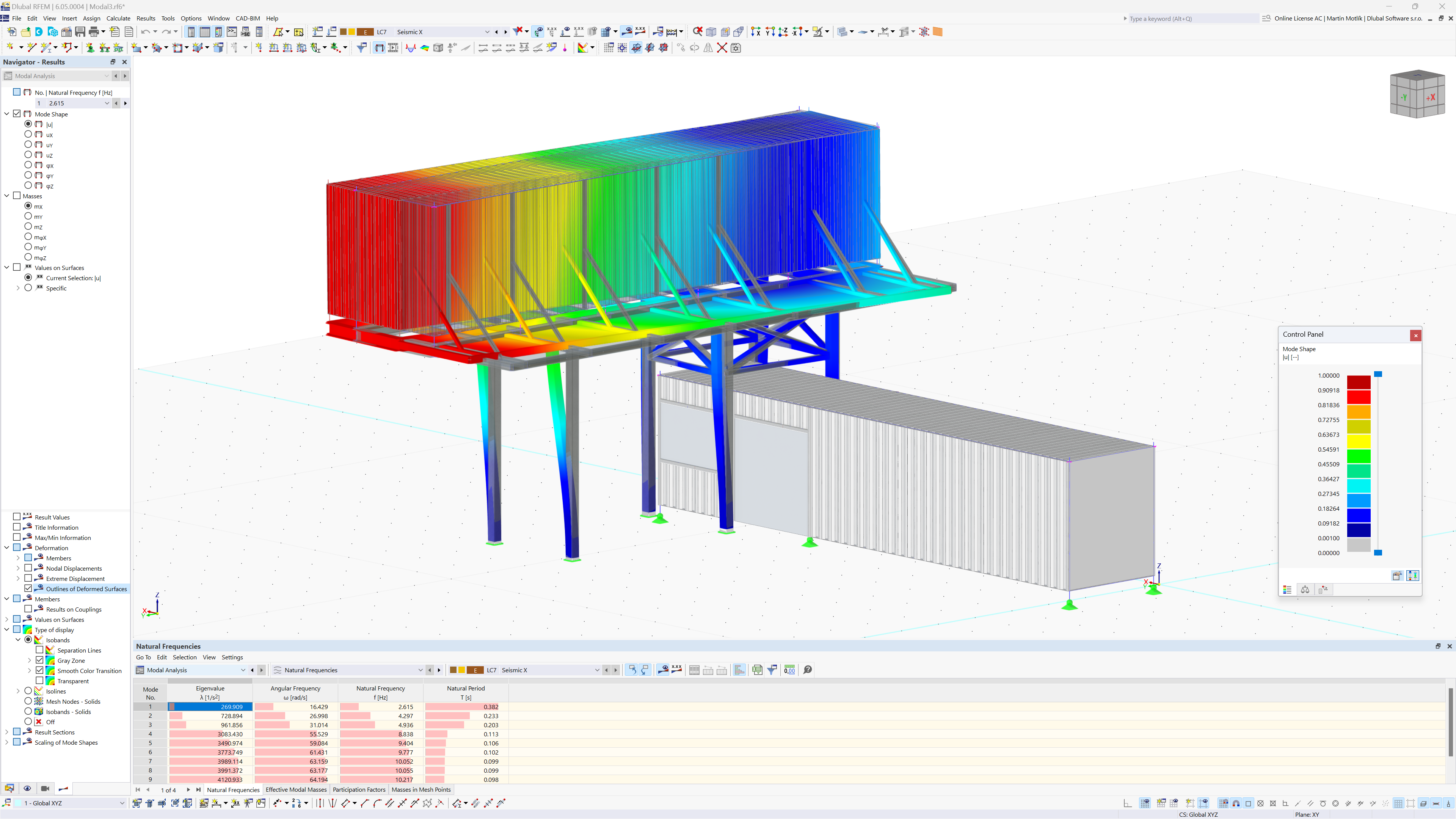
This article explains the different methods available in the Modal Analysis add-on for determining the number of eigenmodes.


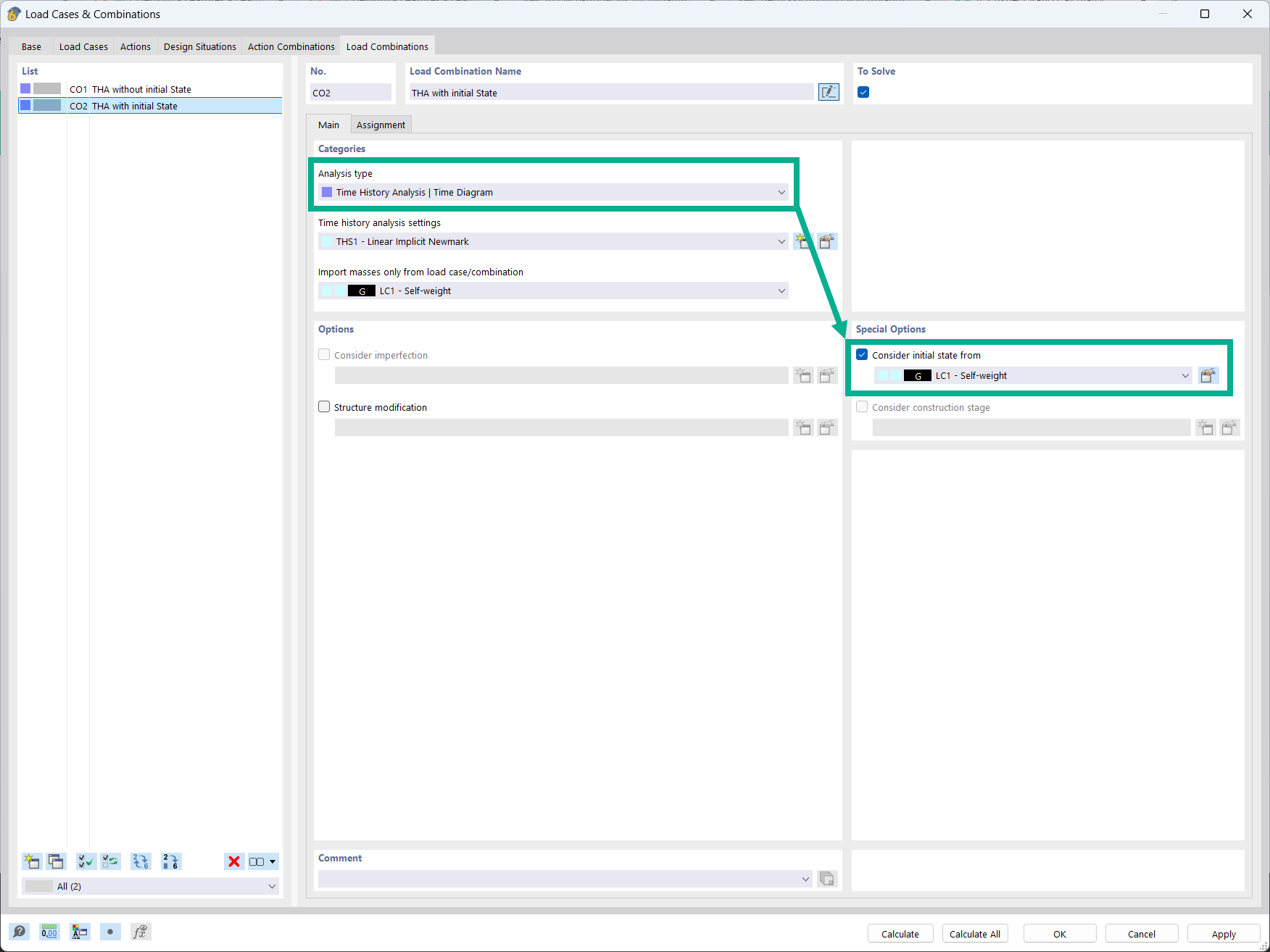
It is possible to consider initial states in the time history analysis.

- Design of five types of seismic force-resisting systems (SFRS) includes Special Moment Frame (SMF), Intermediate Moment Frame (IMF), Ordinary Moment Frame (OMF), Ordinary Concentrically Braced Frame (OCBF), and Special Concentrically Braced Frame (SCBF)
- Ductility check of the width-to thickness ratios for webs and flanges
- Calculation of the required strength and stiffness for stability bracing of beams
- Calculation of the maximum spacing for stability bracing of beams
- Calculation of the required strength at hinge locations for stability bracing of beams
- Calculation of the column required strength with the option to neglect all bending moments, shear, and torsion for overstrength limit state
- Design check of column and brace slenderness ratios

The seismic design result is categorized into two sections: member requirements and connection requirements.
The "Seismic Requirements" include the Required Flexural Strength and the Required Shear Strength of the beam-to-column connection for moment frames. They are listed in the ‘Moment Frame Connection by Member’ tab. For braced frames, the Required Connection Tensile Strength and the Required Connection Compressive Strength of the brace are listed in the ‘Brace Connection by Member’ tab.
The program provides the performed design checks in tables. The design check details clearly display the formulas and references to the standard.

Using the "Damper" member type, you can define a damping coefficient, a spring constant, and a mass. This member type extends the possibilities within the Time History Analysis.
With regard to viscoelasticity, the "Damper" member type is similar to the Kelvin-Voigt model, which consists of the damping element and an elastic spring (both connected in parallel).
How can I display the results of the RF‑/DYNAM Pro add-on module in the printout report?
In the RF-/DYNAM Pro, there is the Rayleigh damping. How do I determine these coefficients, and how are they used?
In RF‑/DYNAM Pro, the "From self-weight of structure" option is available in a mass case. Is it always necessary to activate this option in order to consider the self-weight of the structure?
After running a time history analysis, I am not able to see all results on surfaces. Is there a possibility to show them?
Is it possible to perform a dynamic analysis of the initial deflection of a structural component in RFEM or RSTAB?
How can I consider prestressed cables in RF‑/DYNAM Pro?


_1.jpg?mw=350&hash=ab2086621f4e50c8c8fb8f3c211a22bc246e0552)


Recommended Products for You
RFEM 6 | Main Program RFEM 6

The new generation of 3D FEA software is used for the structural analysis of members, surfaces, and solids.
Price of First License
4,790.00 USD
RFEM 6 | Design

The Concrete Design add-on allows for various design checks according to international standards. You can design members, surfaces, and columns, as well as perform punching and deformation analyses.
Price of First License
2,970.00 USD
RFEM 6 | Additional Analysis

The Construction Stages Analysis (CSA) add-on allows for considering the construction process of structures (member, surface, and solid structures) in RFEM.
Price of First License
1,760.00 USD
RFEM 6 | Additional Analysis

In RFEM, the Geotechnical Analysis add-on uses properties from soil samples to determine the soil body to be analyzed. The accurate determination of soil conditions significantly affects the quality of the structural analysis of buildings.
Price of First License
1,660.00 USD
RFEM 6 | Dynamic Analysis

The Modal Analysis add-on allows for the calculation of eigenvalues, natural frequencies, and natural periods for member, surface, and solid models.
Price of First License
1,360.00 USD
RFEM 6 | Dynamic Analysis

The Response Spectrum Analysis add-on performs seismic analysis using multi-modal response spectrum analysis. The spectra required for this can be created in compliance with the standards or can be user-defined. The equivalent static forces are generated from them. The add-on includes an extensive library of accelerograms from seismic zones that can be used to generate the response spectra.
Price of First License
1,560.00 USD
RFEM 6 | Dynamic Analysis

Using the Pushover Analysis add-on, you can analyze the seismic actions on a particular building, and thus assess whether the building can withstand an earthquake.
Price of First License
1,460.00 USD
RFEM 6 | Special Solutions

The Building Model add-on for RFEM allows you to define and manipulate a building using stories. The stories can be adjusted in many ways afterwards. The information about stories and the entire model (center of gravity) is displayed in tables and graphics.
Price of First License
1,970.00 USD
RFEM 6 | Design

With the Concrete Foundations add-on, you can design square and rectangular individual foundations. In addition to the reinforced concrete design, geotechnical verifications are also carried out. You also determine automatic reinforcement suggestions and receive detailed reinforcement plans and 3D renderings of the foundation structures.
Price of First License
1,260.00 USD
RFEM 6 | Design

The Masonry Design add-on for RFEM allows you to design masonry using the finite element method. It was developed as part of the research project titled DDMaS – Digitizing the Design of Masonry Structures. The material model represents the nonlinear behavior of the brick-mortar combination in the form of macro-modeling.
Price of First License
1,860.00 USD