A deformation calculated with RF‑CONCRETE Members represents a simplified calculation according to the standard. Initially, only the deformation at the point of the maximum loading is calculated. This value and the value of the linear deformation of RFEM or RSTAB at this location are used to calculate a factor. The complete deformation distribution from RFEM or RSTAB will then be multiplied by this factor, then displayed in the results of the add-on module.
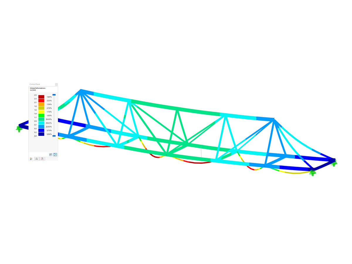
Image 01 shows a comparison of the results of the linear calculation from RFEM and the calculation of the add-on module. In this case, the calculated factor is approximately 2.66.
It is important to note that the deformation can actually only be compared at the location of the maximum deformation. Only there is the calculation actually available. Therefore, various deformations may occur for the connected members, as shown in Image 02.


,_LC1__LI.jpg?mw=350&hash=d5094e5e08f06adf09ec37d550e00fd357782bec)
,_LC1__LI.jpg?mw=350&hash=6ed041c2883863d5ca78996c15f07c7d24cb0baf)
,_LC1__LI.jpg?mw=350&hash=6ed041c2883863d5ca78996c15f07c7d24cb0baf)
,_LC1__LI.jpg?mw=350&hash=6ed041c2883863d5ca78996c15f07c7d24cb0baf)
,_LC1_LI.jpg?mw=350&hash=871f19dacc172cbb19cbdefc7c490c9db999ca2b)




_1.jpg?mw=350&hash=ab2086621f4e50c8c8fb8f3c211a22bc246e0552)







.png?mw=600&hash=49b6a289915d28aa461360f7308b092631b1446e)