
,_LC1__LI.jpg?mw=926&hash=7967d366466f06b0ffd8c2603f2789a9c8ec42c6)
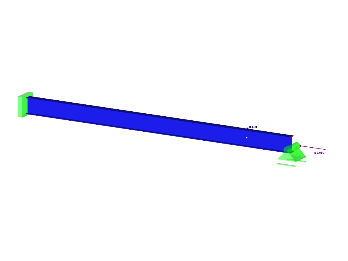
A structure made of I-profile is fully fixed on the left end and embedded into the sliding support on the right end. The structure consists of two segments.
Model Used in
Overall
This page has 0 user ratings.
| 5 star | ||
| 4 star | ||
| 3 star | ||
| 2 star | ||
| 1 star |
Verification Example 000048 | 2
| Number of Nodes | 3 |
| Number of Lines | 2 |
| Number of Members | 2 |
| Number of Surfaces | 0 |
| Number of Solids | 0 |
| Number of Load Cases | 1 |
| Number of Load Combinations | 0 |
| Number of Result Combinations | 0 |
| Dimensions (Metric) | 7.200 x 0.000 x 0.000 m |
| Dimensions (Imperial) | 23.62 x 0 x 0 feet |
You can download this structural model to use it for training purposes or for your projects. However, we do not assume any guarantee or liability for the accuracy or completeness of the model.
Related Models
,_LC1__LI.jpg)

Duration: 00:00:54 min

Duration: 01:19:08 min

Duration: 01:06:17 min
.png?mw=350&hash=c6c25b135ffd26af9cd48d77813d2ba5853f936c)
Duration: 00:08:02 min

Duration: 00:00:47 min

Duration: 00:00:00 min

Duration: 00:00:13 min

Duration: 00:00:29 min

Duration: 00:00:26 min


This article describes and explains the influence of bending stiffness of cables on their internal forces. Furthermore, the text provides information on how this influence can be reduced.
Using the Timber Design add-on, timber column design is possible according to the 2018 NDS standard ASD method. Accurately calculating timber member compressive capacity and adjustment factors is important for safety considerations and design. The following article will verify the maximum critical buckling strength calculated by the Timber Design add-on using step-by-step analytical equations as per the NDS 2018 standard including the compressive adjustment factors, adjusted compressive design value, and final design ratio.
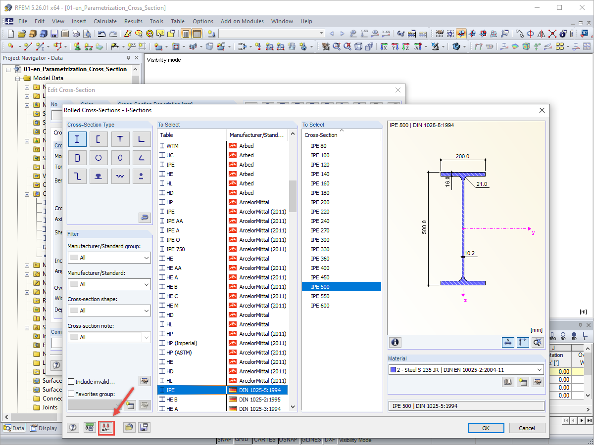
Rolled sections, the most common cross‑section type in RFEM and RSTAB, can also have user‑defined parameters. To do this, select the cross‑section to be modified in the cross‑section library and click the [Parametric Input...] button.
In this article, the adequacy of a 2x4 dimension lumber subject to combined biaxial bending and axial compression is verified using the RF-/TIMBER AWC add-on module. The beam-column properties and loading are based on example E1.8 of AWC Structural Wood Design Examples 2015/2018.


RFEM and RSTAB models can be saved as 3D glTF models (*.glb and *.glTF formats). View the models in 3D in detail with a 3D viewer from Google or Babylon. Take your VR glasses, such as Oculus, to "walk" through the structure.
You can integrate the 3D glTF models into your own websites using JavaScript according to the instructions (as on the Dlubal website Models to Download): "Easily display interactive 3D models on the web & in AR" .
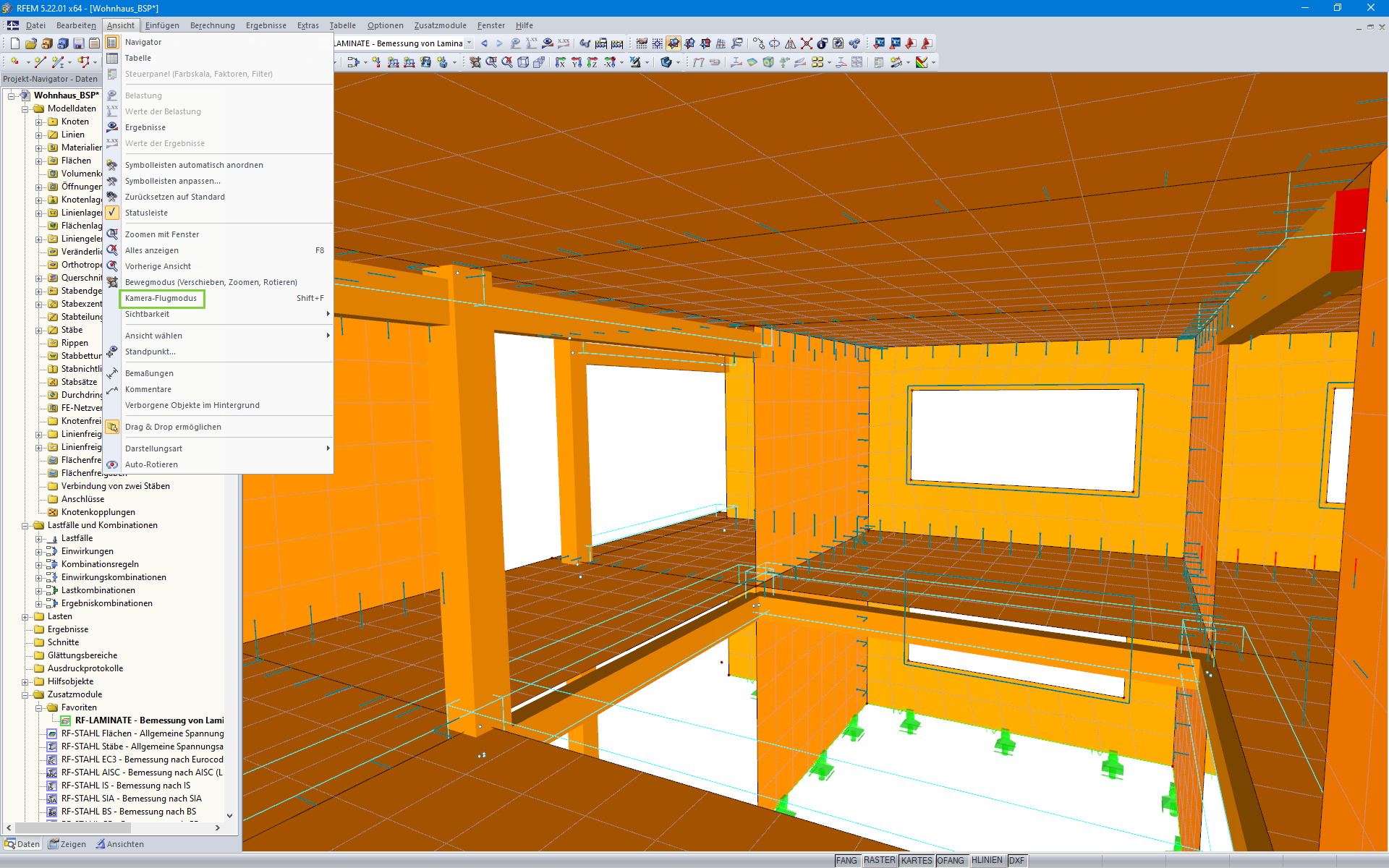
With the Camera Fly Mode view option, you can fly through your RFEM and RSTAB structure. Control the direction and speed of the flight with your keyboard. Additionally, you can save the flight through your structure as a video.
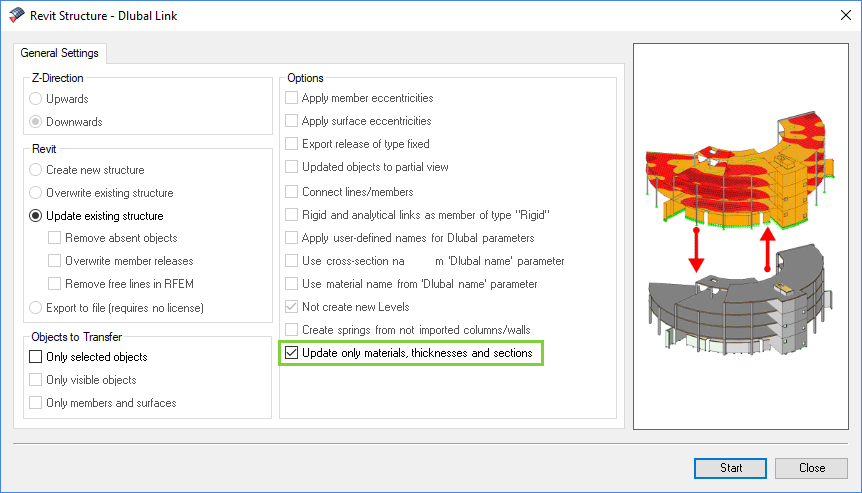
The direct interface with Revit allows you to update the Revit model according to the changes you have made in RFEM or RSTAB. Depending on the modification, the Revit objects may have to be regenerated (deleting the object and subsequent regeneration). The regeneration is performed on the basis of the RFEM/RSTAB model.
If you want to avoid this regeneration, activate the check box 'Update only materials, thicknesses, and sections'. In this case, only the properties of the objects will be adjusted. Changes different from those in material, surface thickness, and section are, however, not considered in this case.
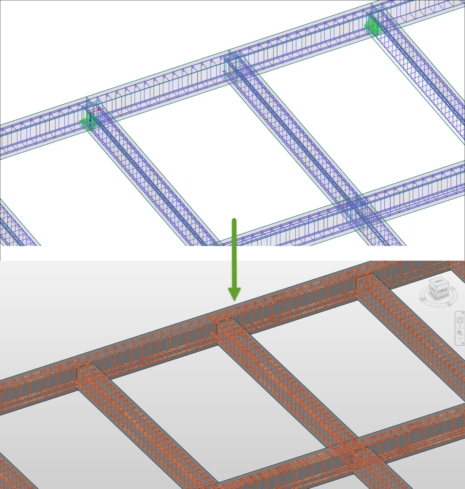
The reinforcement proposal from RF-/CONCRETE Members can be exported to Revit. The rectangular and circular cross-sections are currently supported.
The reinforcement bars can be modified retroactively in Revit.
Where can I find the update reports for RFEM 5, RSTAB 8, SHAPE-THIN, SHAPE-MASSIVE, RX-TIMBER, CRANEWAY, PLATE-BUCKLING, COMPOSITE-BEAM?
For my NVIDIA graphics card, I need to select between a driver from the "Production Branch" and a "New Feature Branch." Which driver is best suited for RFEM/RSTAB?
Why do the min/max values of the total displacement not match the deformations when working with result combinations?
Can I display node coordinates in my model?
Can I use SHAPE-THIN 9 in combination with RSTAB 8?
Has the RF-TOWER add-on module for RFEM 5 already been added to RFEM 6?


_1.jpg?mw=350&hash=ab2086621f4e50c8c8fb8f3c211a22bc246e0552)
Recommended Products for You
RFEM 6 | Main Program RFEM 6

The new generation of 3D FEA software is used for the structural analysis of members, surfaces, and solids.
Price of First License
4,790.00 USD
RFEM 6 | Additional Analysis

The Form-Finding add-on finds the optimal shape of members subjected to axial forces and tension-loaded surface models. The shape is determined by the equilibrium between the member axial force or the membrane stress and the existing boundary conditions.
Price of First License
2,320.00 USD
RFEM 5 | Main Program RFEM

Structural engineering software for a finite element analysis (FEA) of planar and spatial structural systems consisting of plates, walls, shells, members (beams), solids, and contact elements
Price of First License
4,690.00 USD
RFEM 5 | Tensile Membrane Structures

Form-finding of tensile membrane and cable structures
Price of First License
2,320.00 USD
RFEM 5 | Tensile Membrane Structures

Generation of cutting patterns for tensile membrane structures
Price of First License
2,820.00 USD
RFEM 6 | Design

The Steel Design add-on performs the ultimate and serviceability limit state design checks of steel members according to various standards.
Price of First License
2,970.00 USD