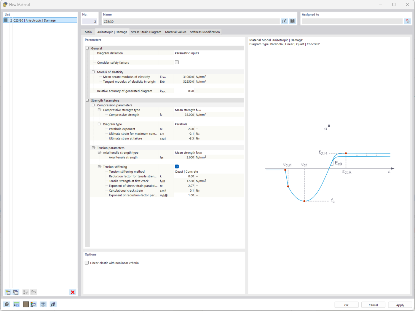
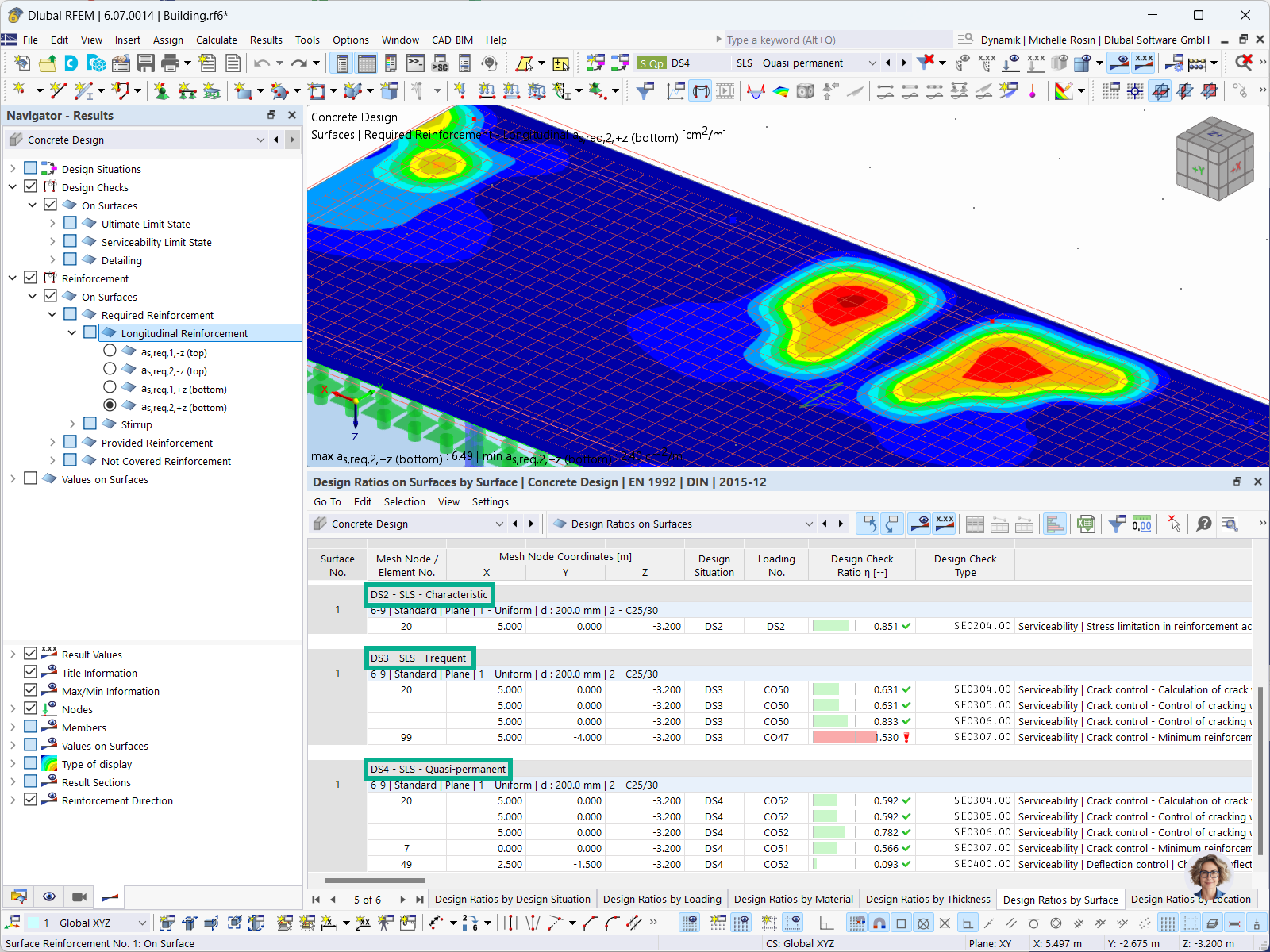
The "Nonlinear Material Behavior" add-on includes the Anistropic | Damage material model for concrete structural components. This material model allows you to consider concrete damage for members, surfaces, and solids.
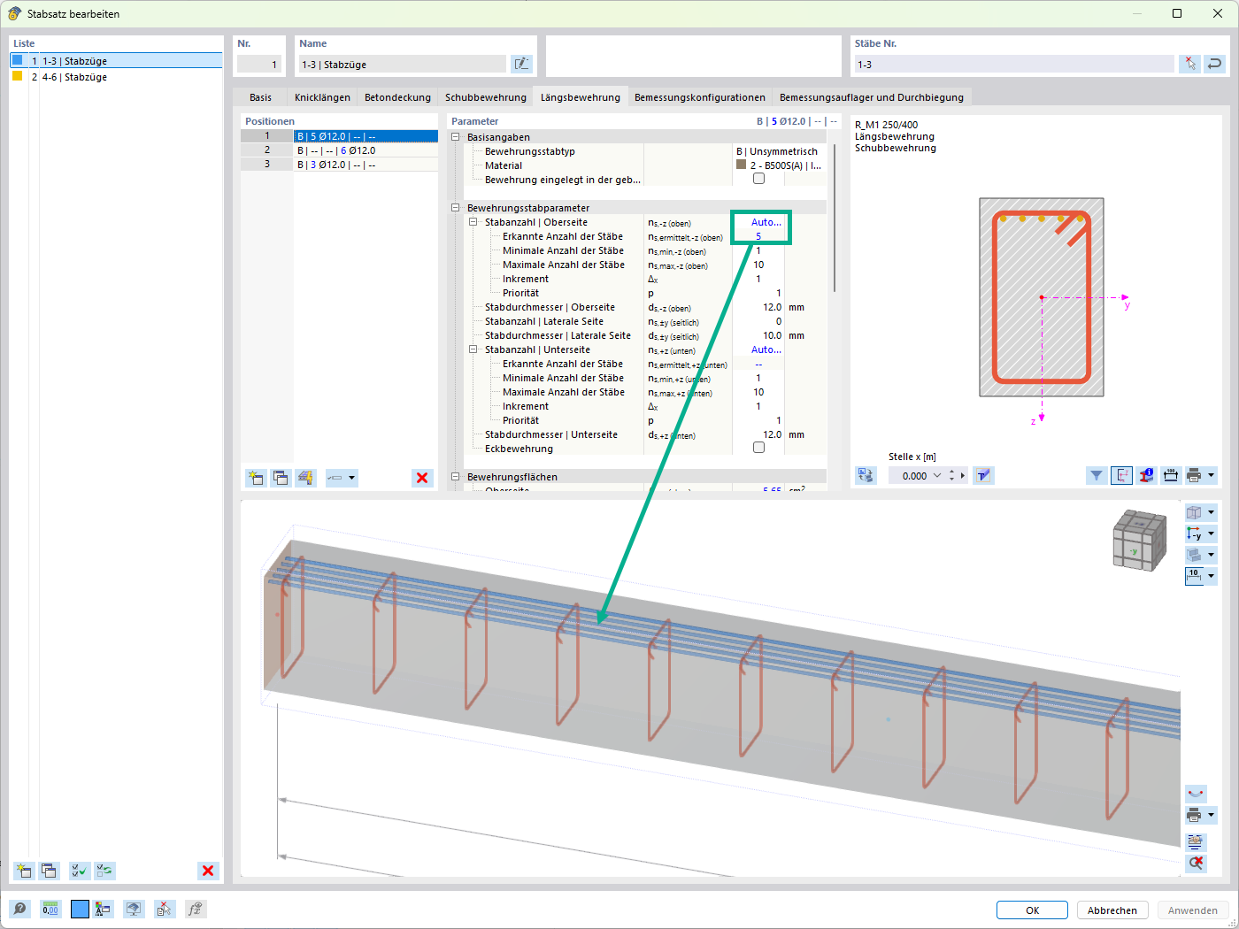
You can define an individual stress-strain diagram via a table, use the parametric input to generate the stress-strain diagram, or use the predefined parameters from the standards. Furthermore, it is possible to consider the tension stiffening effect.
For the reinforcement, both nonlinear material models "Isotropic | Plastic (Members)" and "Isotropic | Nonlinear Elastic (Members)" are available.
It is possible to consider the long-term effects due to creep and shrinkage using the "Static Analysis | Creep & Shrinkage (Linear)" analysis type that has been recently released. Creep is taken into account by stretching the stress-strain diagram of the concrete using the factor (1+phi), and shrinkage is taken into account as the pre-strain of the concrete. More detailed time step analyses are possible using the "Time-Dependent Analysis (TDA)" add-on.


.png?mw=512&hash=4a84cbc5b1eacf1afb4217e8e43c5cb50ed8d827)


.jpg?mw=350&hash=13c1866b992b7c0d6754ad58cc10434a5b3fe8e7)
.jpg?mw=350&hash=e036680c49a47e8bd426d4d54e7f1b2ba5eb927c)


-querkraft-hertha-hurnaus.jpg?mw=350&hash=3306957537863c7a7dc17160e2ced5806b35a7fb)


.png?mw=350&hash=87067b88e84e78e23f7a538dec586f8442297bd4)


.png?mw=600&hash=49b6a289915d28aa461360f7308b092631b1446e)
