The shear force resistance VRd,c without computational shear force reinforcement according to 6.2.2 of EN 1992-1-1 [1] or 10.3.3 of DIN 1045-1 [2] is calculated depending on the longitudinal reinforcement ratio. If the required longitudinal reinforcement from the bending design is used for the calculation of VRd, c, this leads to an underestimation of the shear force resistance without shear reinforcement in the vicinity of the hinged end supports. In contrast to the shear force, the required bending reinforcement decreases in the direction of the support. In addition, the actually inserted longitudinal reinforcement usually deviates significantly from the required bending reinforcement in the end support area (for example, in the case of non-staggered beam reinforcement).
KB 000655 | Determining Required Longitudinal Reinforcement for Shear Force Design According to EN 1992-1-1
- Deutsches Institut für Normung e.V. (DIN). (2010). National Annex – Nationally determined parameters – Eurocode 2: Design of concrete structures – Part 1‑1: General rules and rules for buildings; DIN EN 1992‑1‑1/NA:2013‑04. Berlin: Beuth Verlag GmbH.
- DIN 1045-1: Concrete, Reinforced and Prestressed Concrete Structures Part 1-1: Bemessung und Konstruktion, Kommentierte Kurzfassung. Beuth Verlag GmbH, Berlin, edition = 2. 2005.


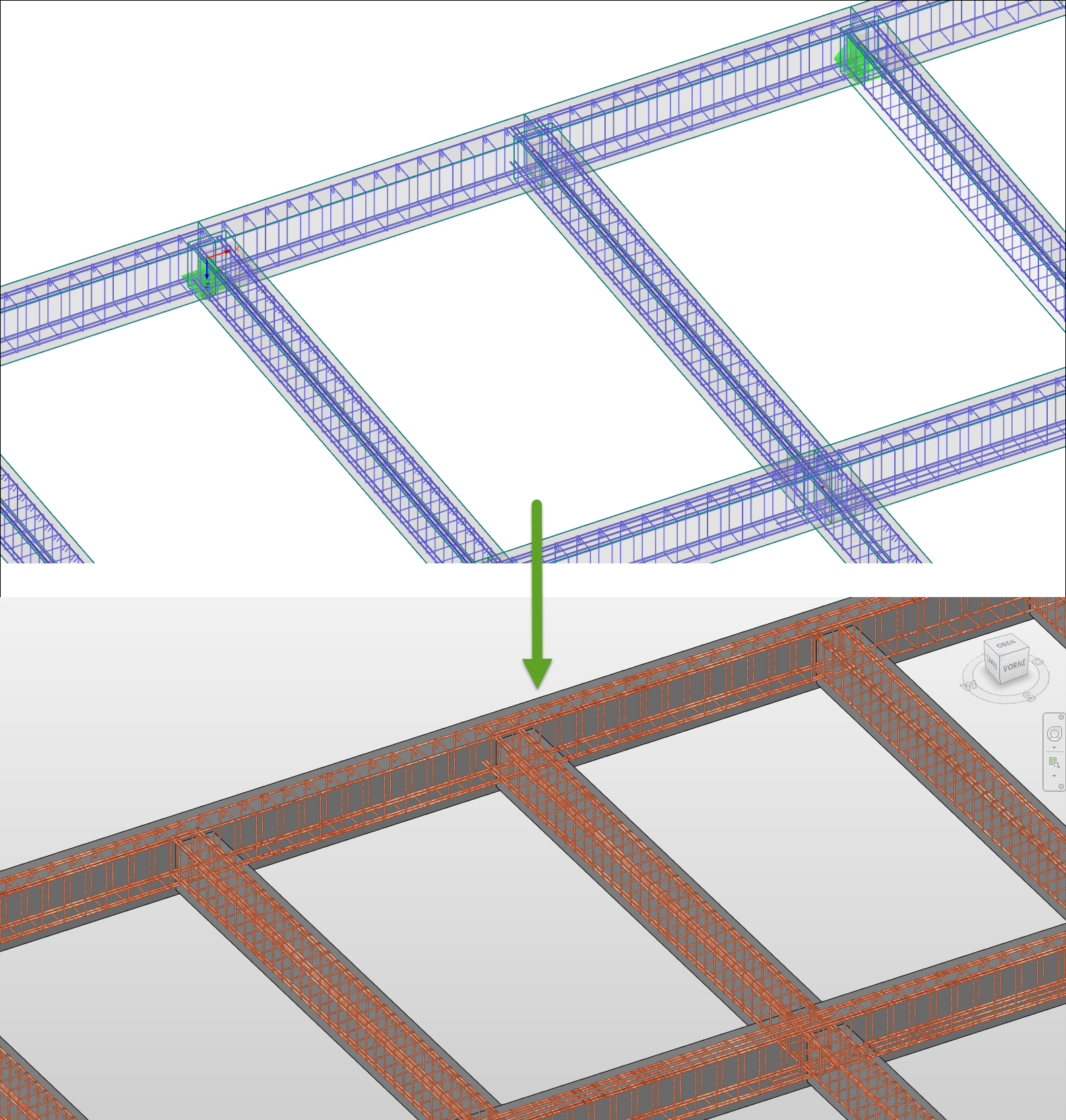
The reinforcement proposal from RF-/CONCRETE Members can be exported to Revit. The rectangular and circular cross-sections are currently supported.
The reinforcement bars can be modified retroactively in Revit.

- Import of cross-sections, materials, and loads from RFEM
- Input of straight and parabolic tendons, layout definition of prestressing steel
- Automatic calculation of prestressing forces and equivalent member loads
- Transfer of equivalent loads to RFEM
- Consideration of short-term losses resulting due to friction, anchorage slippage, relaxation, elastic deformation of concrete, and so on
- Results of tendon strains before and after anchorage
- Calculation of the minimum and maximum stresses in tendons
- Internal forces results in defined sections
- Optional calculation of RF-TENDON Design in background
- Clear representation of tendon layout in 3D rendering
- Printout or RTF export of results
- Settings of display parameters and units (metric or imperial, decimal places etc.)
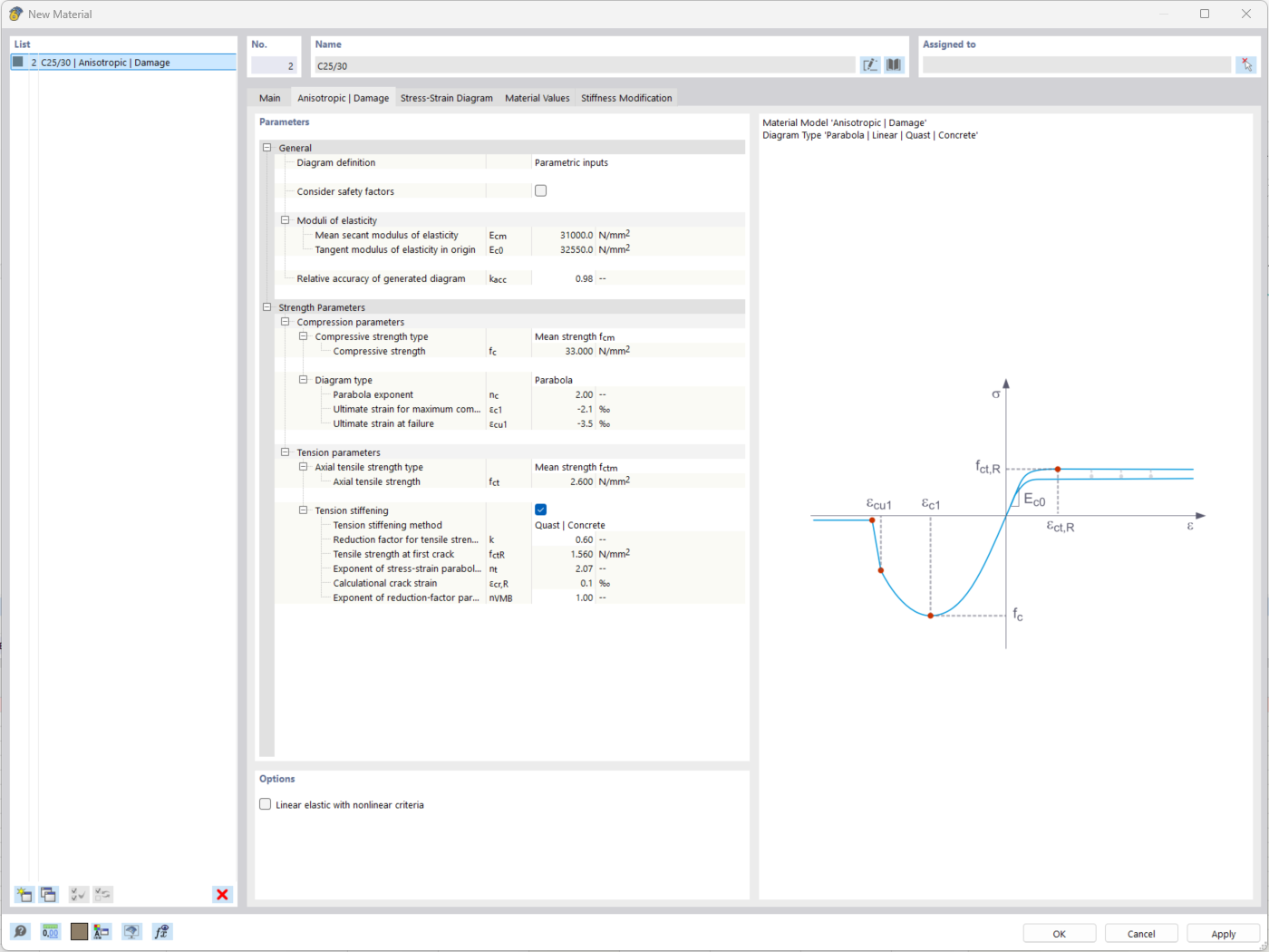
The "Nonlinear Material Behavior" add-on includes the Anistropic | Damage material model for concrete structural components. This material model allows you to consider concrete damage for members, surfaces, and solids.
You can define an individual stress-strain diagram via a table, use the parametric input to generate the stress-strain diagram, or use the predefined parameters from the standards. Furthermore, it is possible to consider the tension stiffening effect.
For the reinforcement, both nonlinear material models "Isotropic | Plastic (Members)" and "Isotropic | Nonlinear Elastic (Members)" are available.
It is possible to consider the long-term effects due to creep and shrinkage using the "Static Analysis | Creep & Shrinkage (Linear)" analysis type that has been recently released. Creep is taken into account by stretching the stress-strain diagram of the concrete using the factor (1+phi), and shrinkage is taken into account as the pre-strain of the concrete. More detailed time step analyses are possible using the "Time-Dependent Analysis (TDA)" add-on.
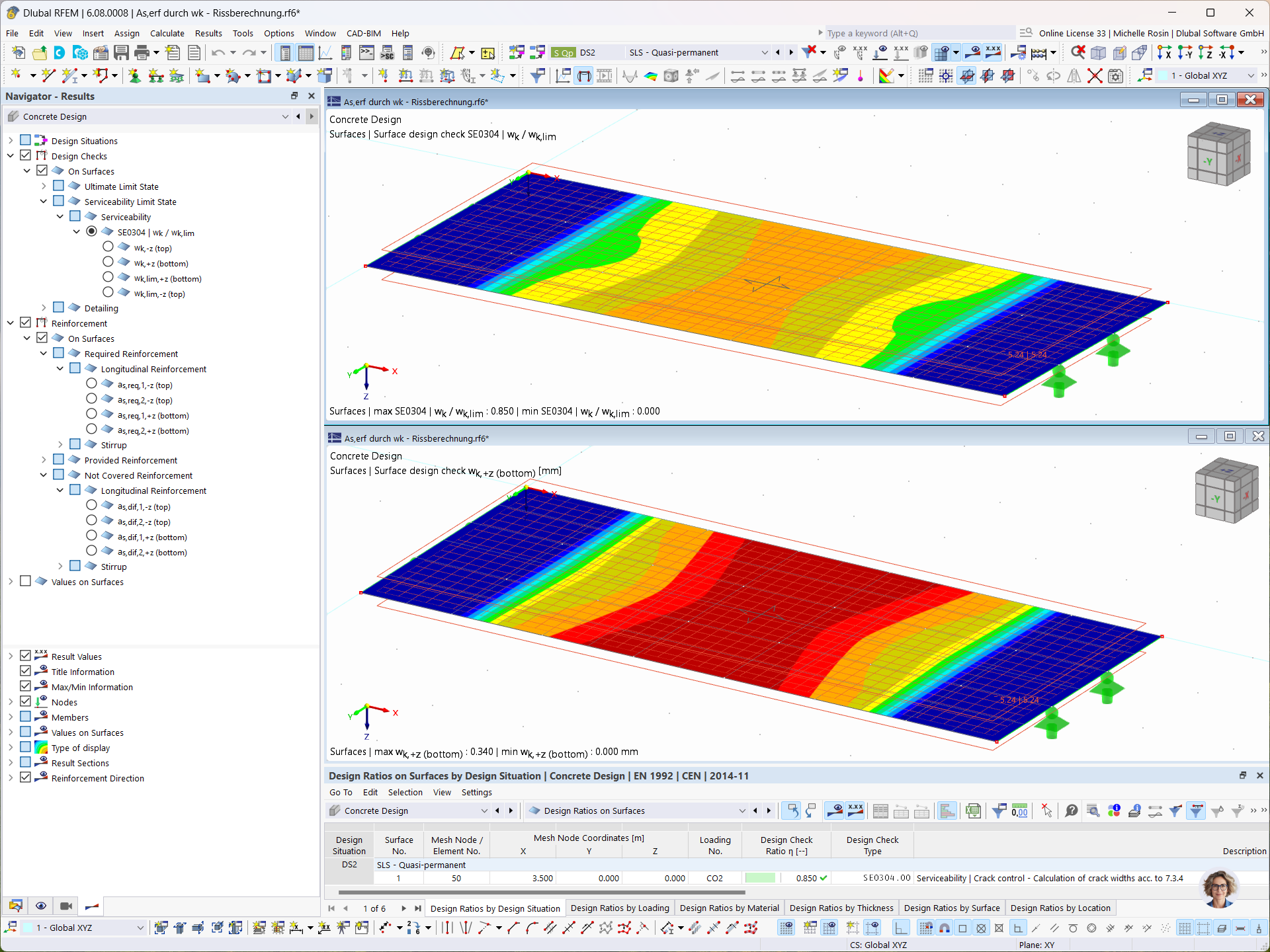
In the Concrete Design add-on, you can determine the required longitudinal reinforcement for the direct crack width analysis (w k).


_1.jpg?mw=350&hash=ab2086621f4e50c8c8fb8f3c211a22bc246e0552)


-querkraft-hertha-hurnaus.jpg?mw=350&hash=3306957537863c7a7dc17160e2ced5806b35a7fb)


