When defining the effective slab width of T-beams, RFEM provides the predefined widths, which are determined with 1/6 and 1/8 of the member length. The background to these two factors is explained in detail.
KB 000483 | Background Knowledge for Definition of Effective Slab Width Used for T-beams
Links

In addition to the result tables, you can create three-dimensional graphics in RF‑/FRAME‑JOINT Pro and RF‑/JOINTS. This is a realistic representation of a connection to scale.

In this example, the design resistance of an end plate according to EN 1993-1-8 [1] is to be determined; the other components are not described here. To check the results, the dimensions of the connection IH 3.1 B 30 24 of Typified Connections [2] were used. S 235 material and bolts with strength 10.9 are used.

When designing bending-resistant connections from I-beams, the connection is dissolved into the individual parts. For these basic components of a joint, there are separate formula calculators for load-bearing capacity and stiffness. In RFEM and RSTAB, frame joints can be designed using the RF-/FRAME-JOINT Pro add-on module.
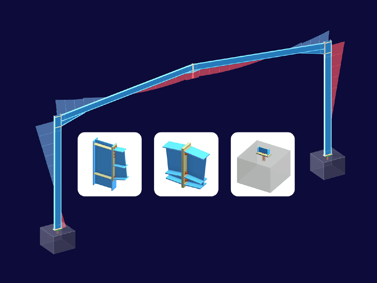
This article explores the importance of considering joint-structure interaction in modeling and design and how to do it in RFEM 6.
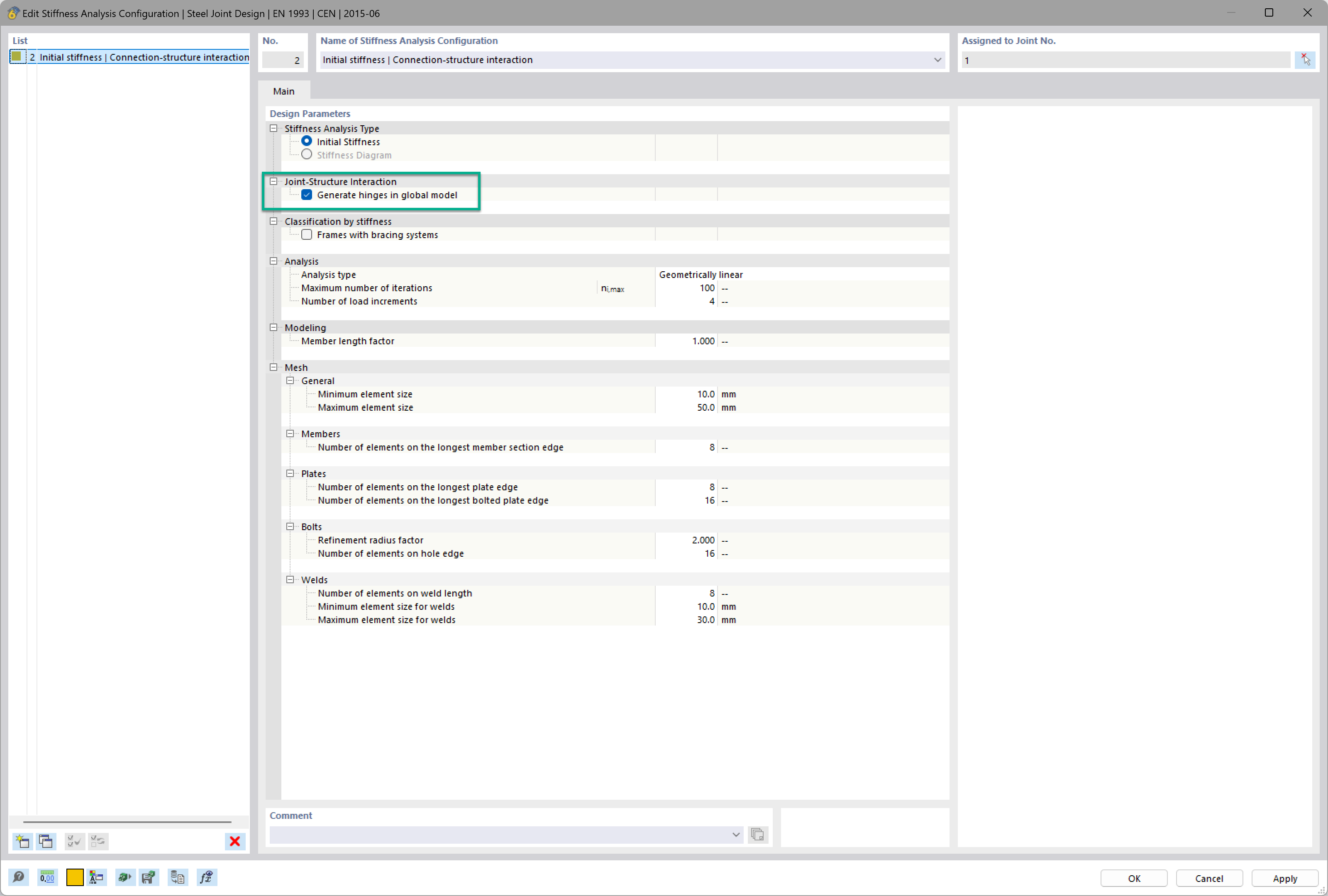
Want to automatically consider steel joint stiffness in your global RFEM model? Utilize the Steel Joints add-on!
Activate joint-structure interaction in the stiffness analysis of your steel joints. Hinges with springs are then automatically generated in the global model and included in subsequent calculations.
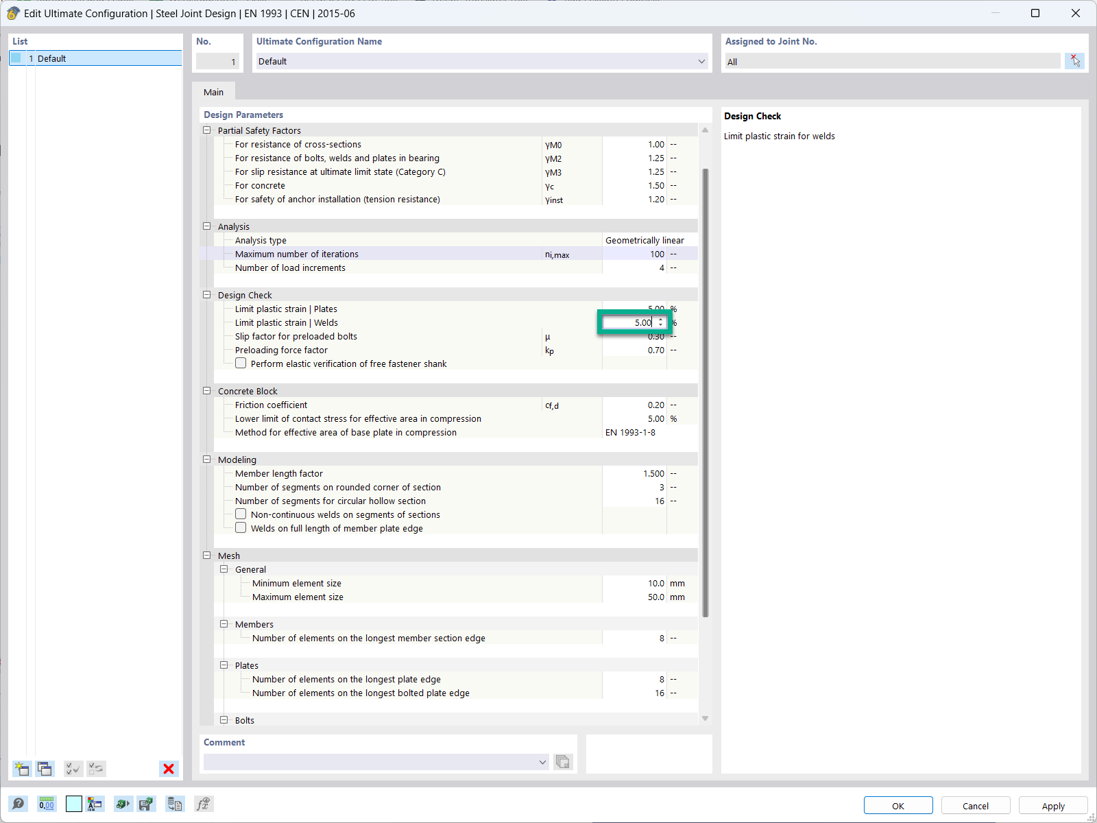
In the ultimate configuration of the steel joint design, you have the option to modify the limit plastic strain for welds.
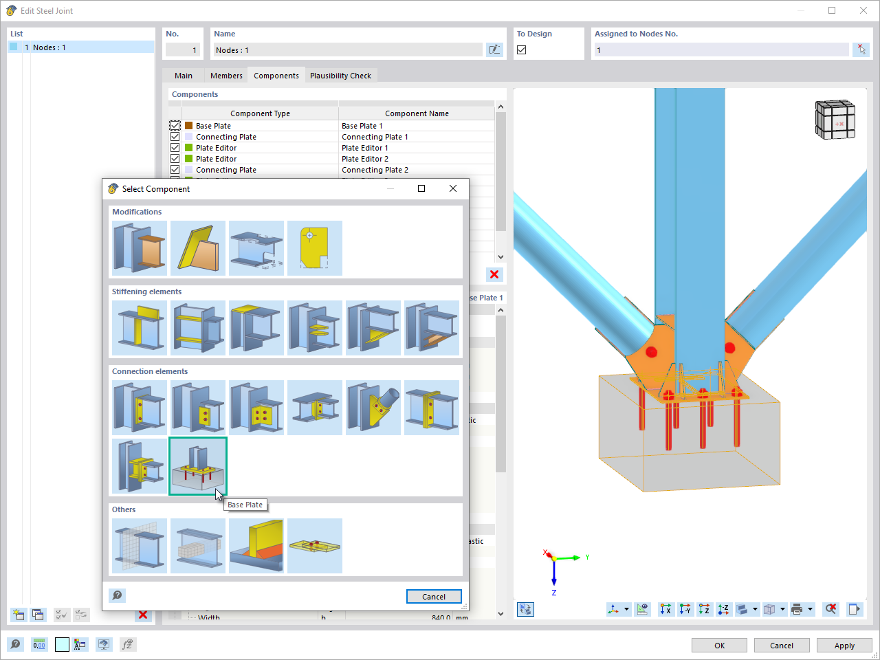
The "Base Plate" component allows you to design base plate connections with cast-in anchors. In this case, plates, welds, anchorages, and steel-concrete interaction are analyzed.
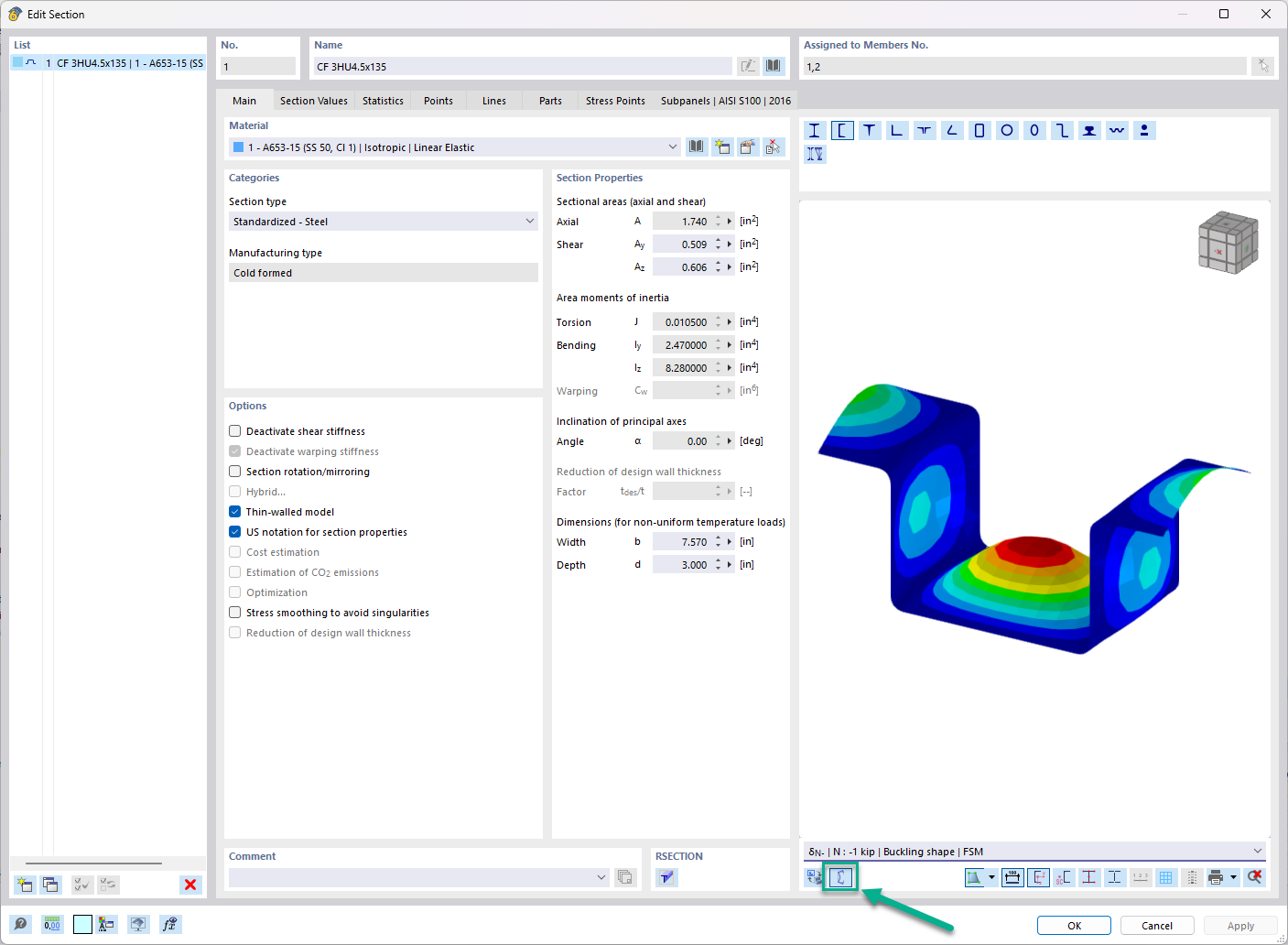
In the "Edit Section" dialog box, you can display the buckling shapes of the Finite Strip Method (FSM) as a 3D graphic.
When calculating a connection using the FRAME‑JOINT Pro add-on module, a message appears saying that the value is out of the valid range (existing value: 108, minimum value 100, maximum value 100). What does this message mean?
For design in FRAME‑JOINT Pro, I get Error No. 30011 "The selected nodes have different geometry […]." How can I design my connection?
When modeling a beam connection to a continuous column, I have the problem that the column flange fails under bending. If I add backing plates in the FRAME‑JOINT Pro add-on module, nothing changes for all design ratios. What is the problem here?
Is it possible to use one of the RFEM 5 / RSTAB 8 add-on modules to design a frame joint with a docked beam, stiffeners, and any number of bolt rows?
My connection cannot be designed due to an incorrect geometry input. What can I do?
I am copying a design case and/or selecting a different or further node for the design. However, the connection geometry defined in the previous design case is not transferred. Why?
Recommended Products for You


.png?mw=350&hash=c6c25b135ffd26af9cd48d77813d2ba5853f936c)


_1.jpg?mw=350&hash=ab2086621f4e50c8c8fb8f3c211a22bc246e0552)


.png?mw=600&hash=49b6a289915d28aa461360f7308b092631b1446e)


