

Punching shear design for a central column in a flat slab.
Overall
This page has 0 user ratings.
| 5 star | ||
| 4 star | ||
| 3 star | ||
| 2 star | ||
| 1 star |
Verification Example 1028
| Number of Nodes | 6 |
| Number of Lines | 5 |
| Number of Members | 1 |
| Number of Surfaces | 1 |
| Number of Solids | 0 |
| Number of Load Cases | 1 |
| Number of Load Combinations | 1 |
| Number of Result Combinations | 0 |
| Total Weight | 21.707 tons |
| Dimensions (Metric) | 5.000 x 4.000 x 7.000 m |
| Dimensions (Imperial) | 16.4 x 13.12 x 22.97 feet |
You can download this structural model to use it for training purposes or for your projects. However, we do not assume any guarantee or liability for the accuracy or completeness of the model.

Duration: 00:00:27 min

Duration: 00:00:22 min

Duration: 00:00:25 min

Duration: 00:00:05 min

Duration: 00:00:24 min
Duration: 00:00:30 min

Duration: 00:00:10 min

Duration: 00:00:05 min

Duration: 00:00:11 min


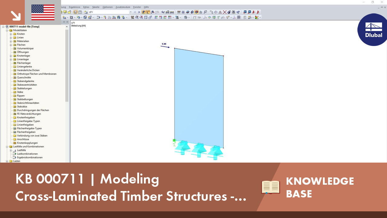
One of the advantages of entering the structure in RFEM is the complete freedom when selecting the geometry. You can easily select a structure where re‑entrant rolling corners are given as shown in the image.
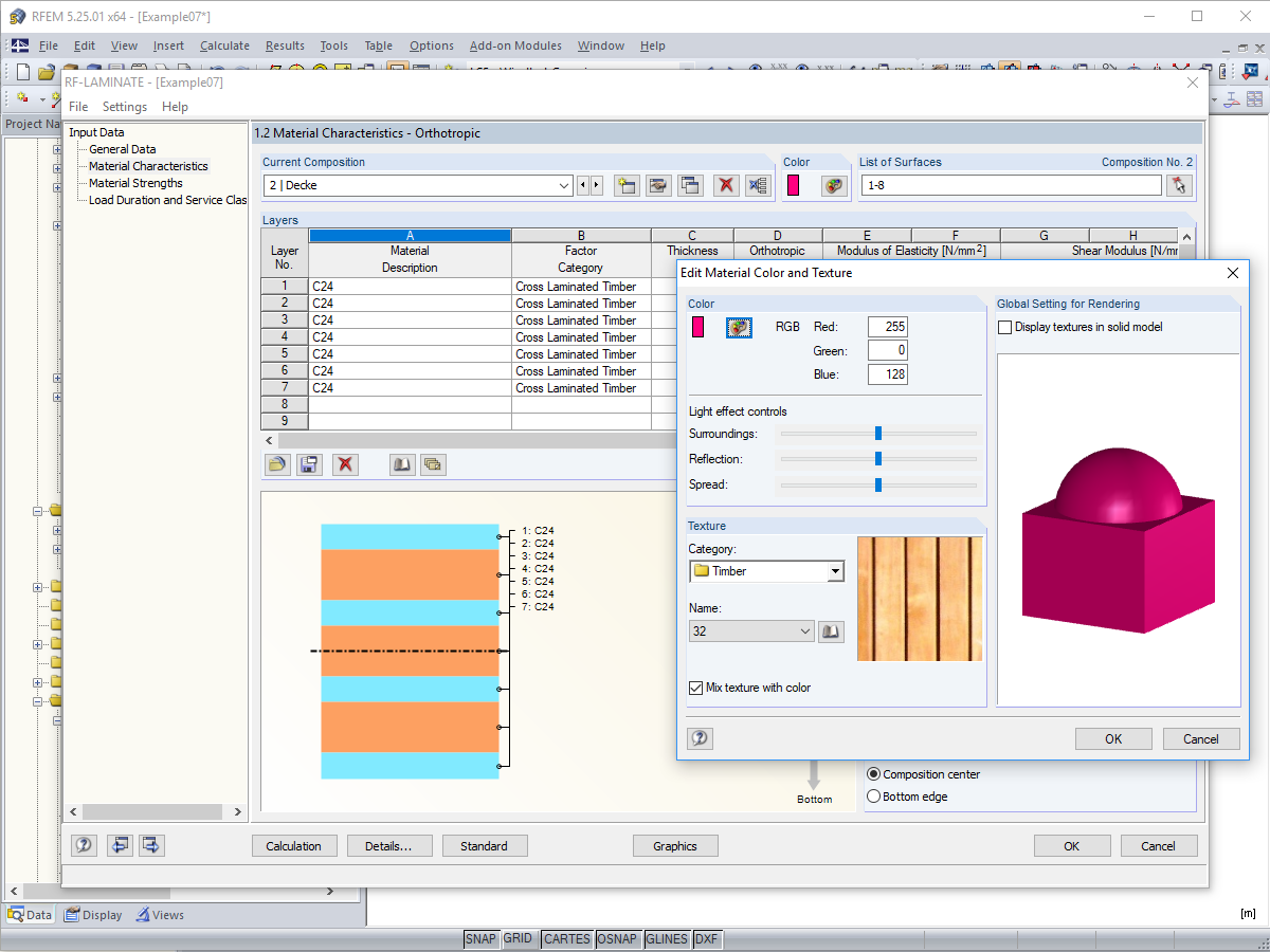
To better distinguish between the different layer compositions (for example, for walls and ceilings), you can assign user‑defined colors and textures to each composition.

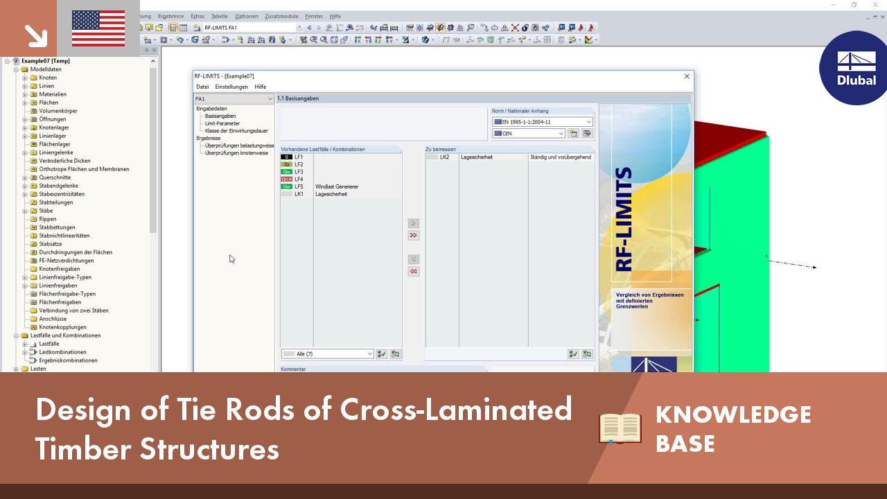
In this article, we will look at the design of shear connectors of cross‑laminated timber structures that transfer the longitudinal forces of the shear wall to the soil.

Usually, the lifting forces acting on a structure, which mostly result from wind loads or a dynamic analysis, are transferred into the ground through ties.


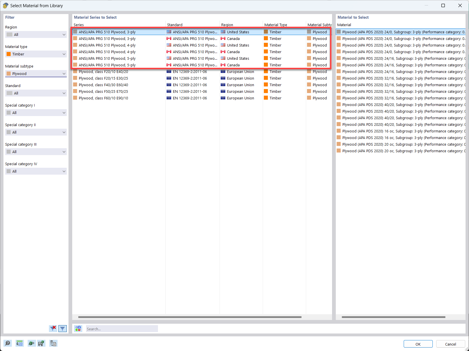
In the material library of RFEM, you can find plywood materials according to the US and Canadian standards ANSI/APA PRG 510 Plywood (USA/CAN).
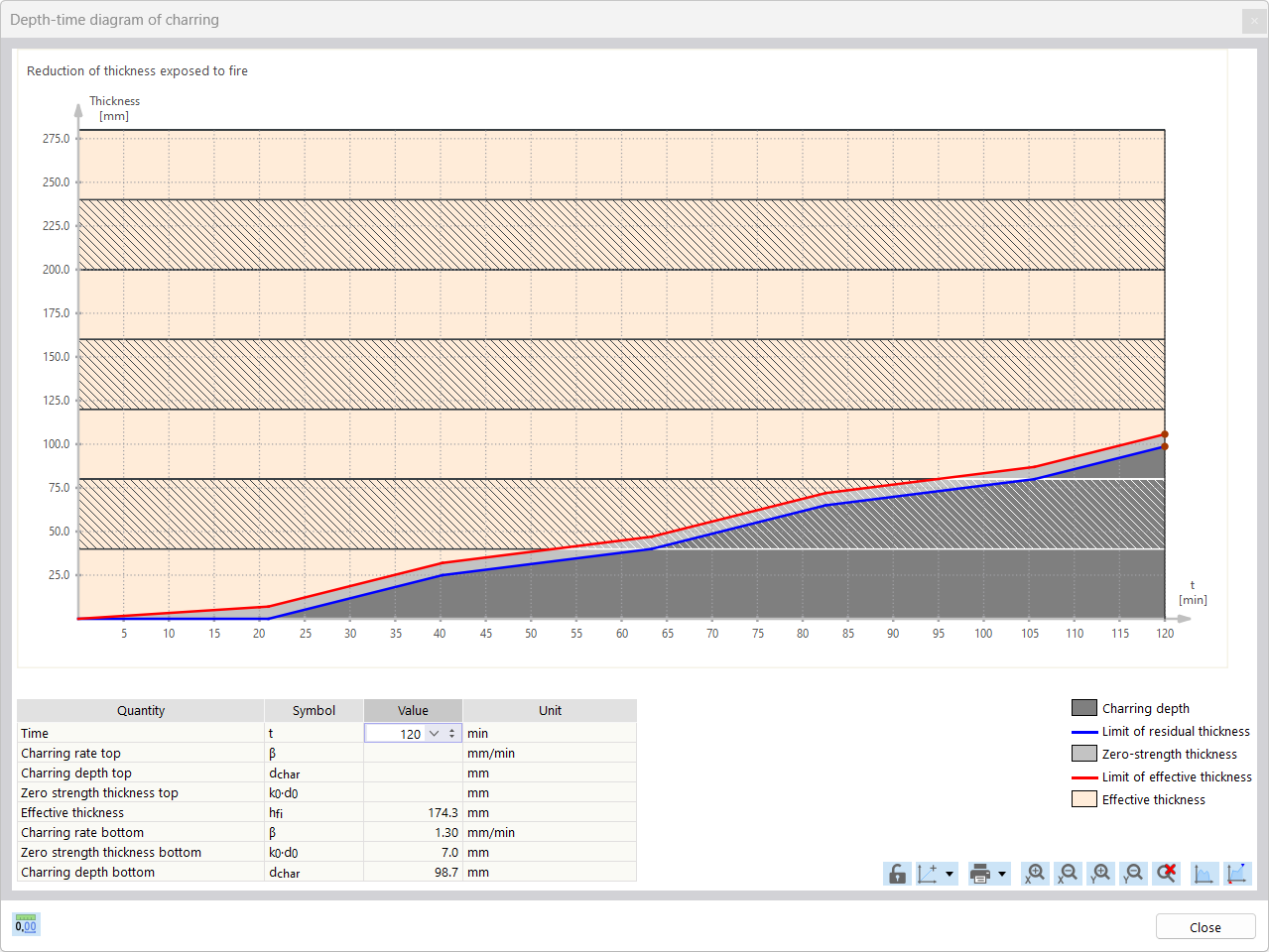
For the fire resistance design of timber surfaces, you can display a charring diagram depending on the time of fire exposure.
It is also possible to print this charring diagram into the printout report.
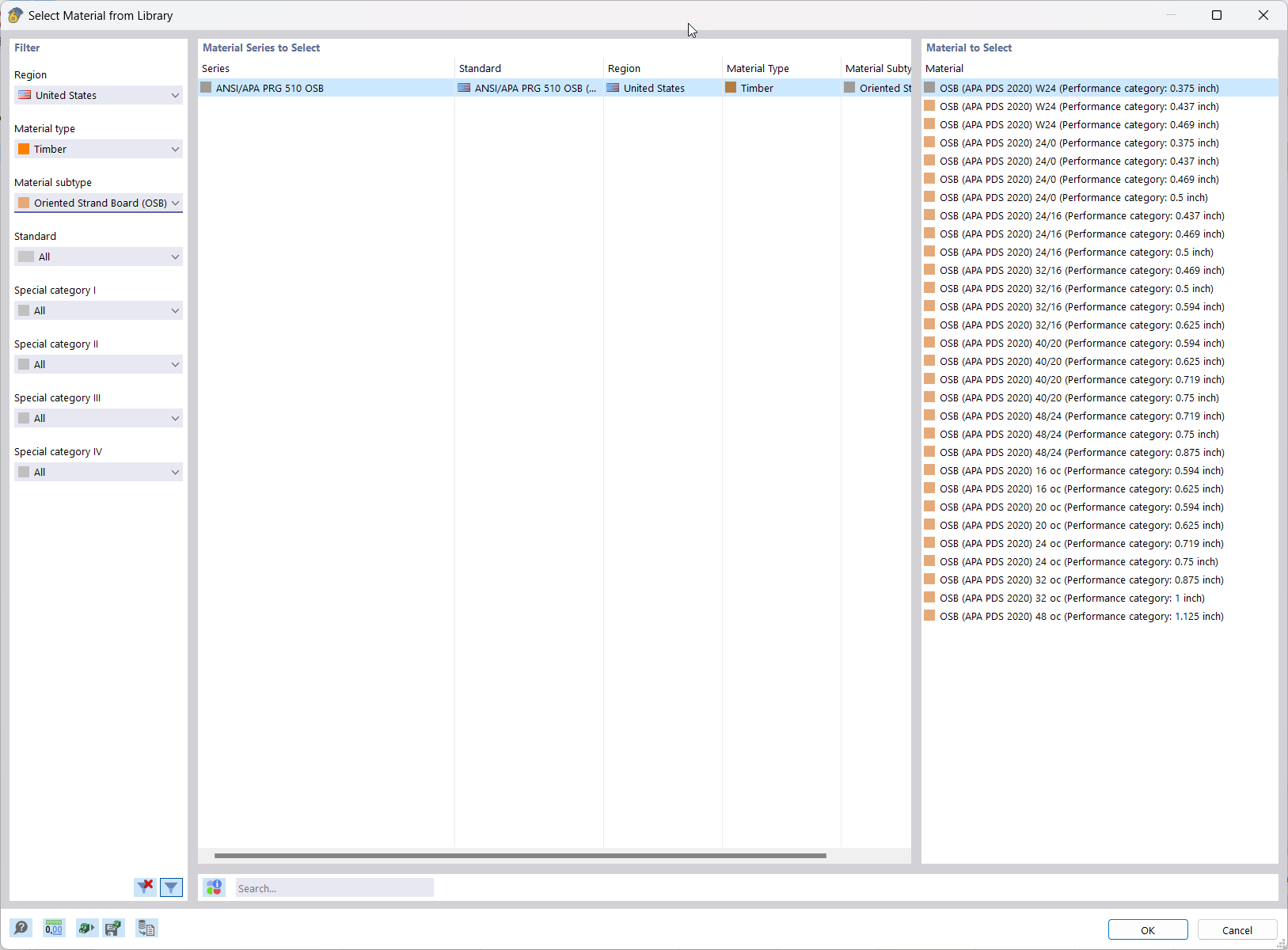
In RFEM, the oriented strand board (OSB) material is available for the USA and Canada. The material parameters are taken from the "Panel Design Specification manual".

Using the "Beam Panel" thickness type, you can model timber panel elements in 3D space. Simply specify the surface geometry and the timber panel elements are automatically generated using an internal member-surface construct, including the element connection stiffness. The Beam Panel thickness type is defined using the Multilayer Surfaces add-on.
A "beam panel" provides you with the following advantages:
- Single-sided or double-sided sheathing
- Automatic calculation of a semi-rigid coupling between studs and sheathing
- Nailed sheathing connection
- Stapled sheathing connection
- User-defined sheathing connection
- Representation as a complete geometric 3D object (frame, studs, surface, etc.), including eccentricity and automatically calculated stiffness between elements
- Consider openings via surface cells
- Design of the individual structural elements utilizing the Timber Design add-on (full shear wall design planned for a future release)
- Other material options available (e.g., particle board, gypsum, or fiberboard sheathing with cold-formed steel sections)
How does the "Orthotropic Plastic" material model work in RFEM?
How is it possible to display the RF‑LAMINATE library? We would like to check that it is up to date.
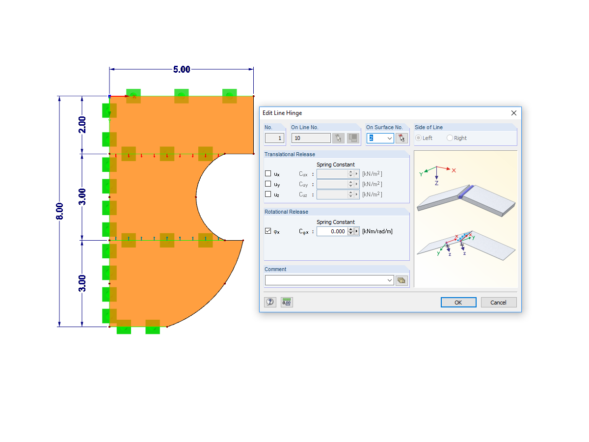
Can I use surface releases to separate two overlapping surfaces?
Do I need to add a line hinge/line release for the CLT wall-to-floor connection in the Building Model add-on?
How can I add counteracting dead loads (0.9*D) in NBC load combinations?
How can I perform member design by case for different settings in the design configuration?


