

This thesis is focused on the comparison of connection design using the component method and the finite element method. The introduction of this thesis deals with a summary of the issues of designing the end plate bolted connections using components and finite elements. An analytical model simulating the real connection is divided into main components, whose resistance, stiffness, and deformation capacity are derived according to the mechanical principles and its loading.
Model Used in
Overall
This page has 0 user ratings.
| 5 star | ||
| 4 star | ||
| 3 star | ||
| 2 star | ||
| 1 star |
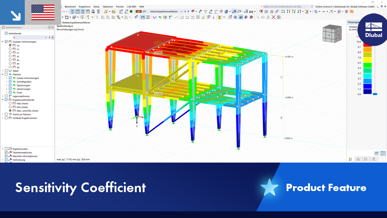
Possibility of Setting Stiffness and Resistance of Frame Corner by Analytical and Numerical Method
No Download Possible
Customer Project / View Only
| Number of Nodes | 142 |
| Number of Lines | 152 |
| Number of Members | 10 |
| Number of Surfaces | 67 |
| Number of Solids | 1 |
| Number of Load Cases | 3 |
| Number of Load Combinations | 2 |
| Total Weight | 0.788 tons |
| Dimensions (Metric) | 2.004 x 0.410 x 1.877 m |
| Dimensions (Imperial) | 6.57 x 1.35 x 6.16 feet |
| Program Version | 4.10.19 |

Duration: 01:14:03 min

Duration: 00:00:56 min

Duration: 00:02:14 min

Duration: 00:03:19 min

Duration: 00:01:06 min

Duration: 00:00:55 min
Duration: 00:00:32 min

Duration: 00:57:23 min

Duration: 00:38:40 min


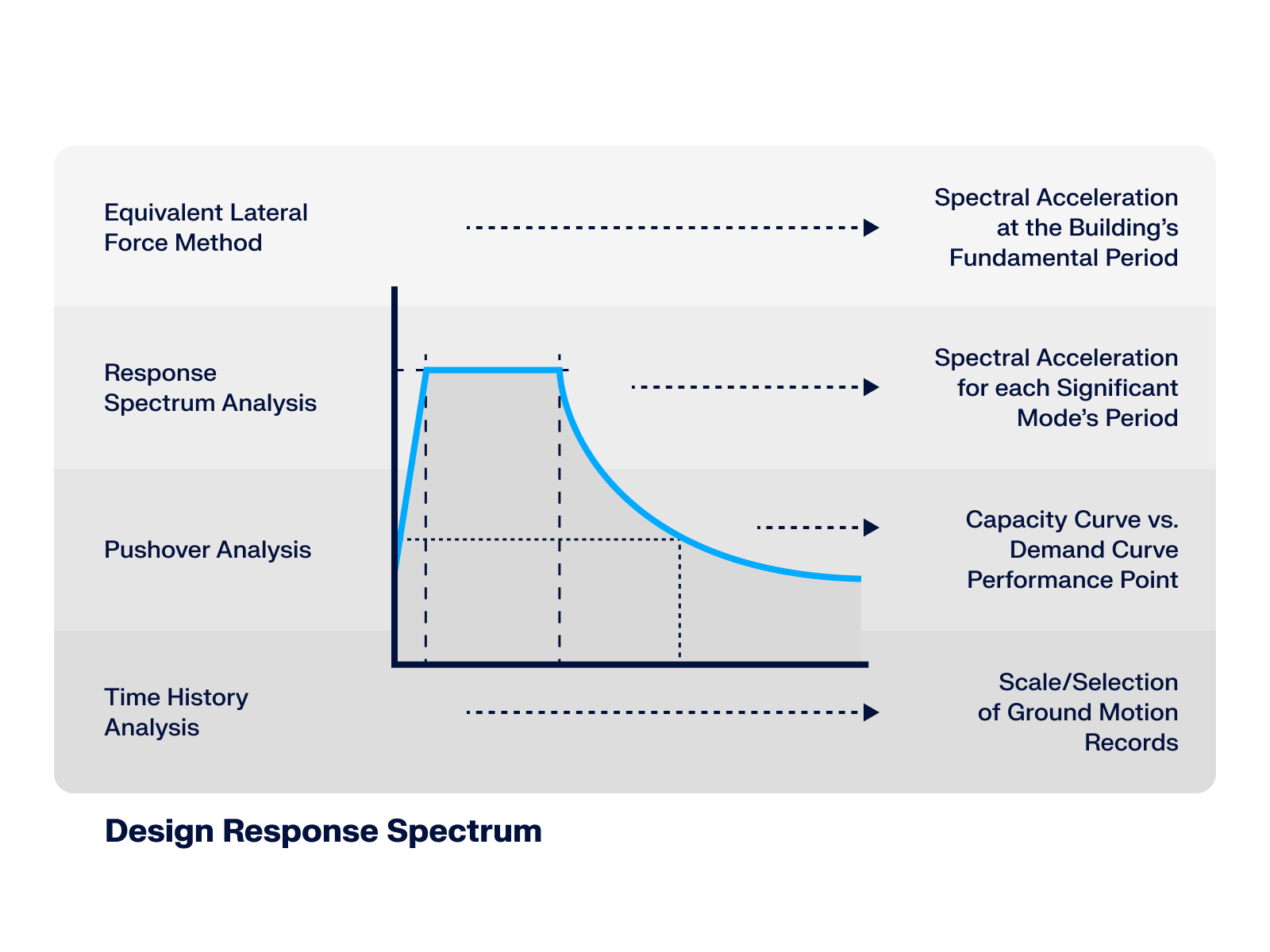
This article* explores the role of the Design Response Spectrum across different seismic analysis methods, demonstrating its significance from simplified static approaches up to advanced dynamic simulations.
.png?mw=512&hash=71474bbf484eff50cf2eb4da2f7c0a5d6103a65d)
This article provides an overview of RFEM 6 and RSTAB 9's dynamic analysis capabilities, highlighting essential add-ons and learning resources for seismic analysis, vibration-resistant design, and structural dynamics applications.
.png?mw=512&hash=4a84cbc5b1eacf1afb4217e8e43c5cb50ed8d827)
This article provides a comprehensive overview of essential seismic analysis methods, explaining their principles and applications, as well as the scenarios in which they are most effective

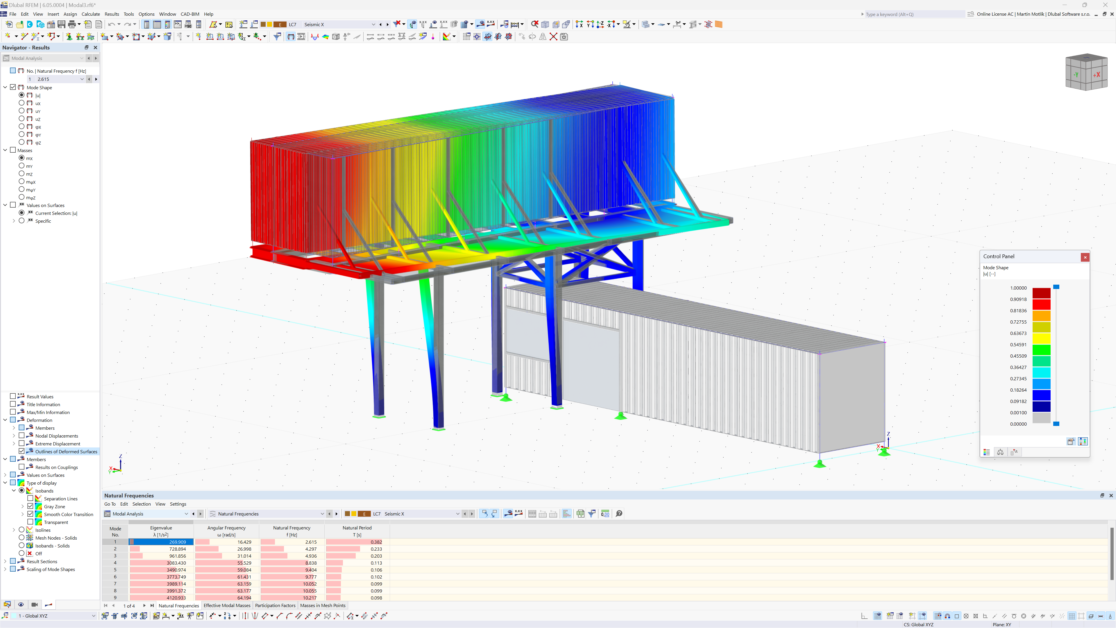
This article explains the different methods available in the Modal Analysis add-on for determining the number of eigenmodes.


.png?mw=350&hash=fe466497477280889b4e8c8ddb1890d8eb1c8100)

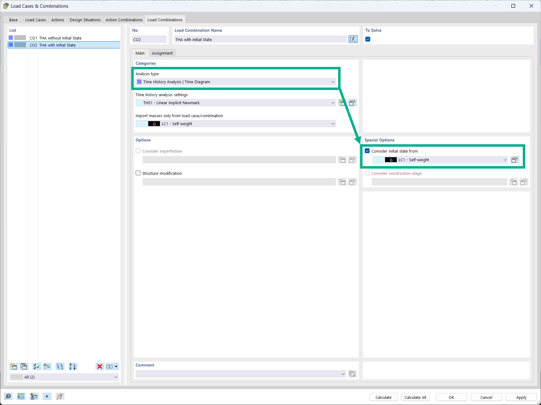
It is possible to consider initial states in the time history analysis.

- Design of five types of seismic force-resisting systems (SFRS) includes Special Moment Frame (SMF), Intermediate Moment Frame (IMF), Ordinary Moment Frame (OMF), Ordinary Concentrically Braced Frame (OCBF), and Special Concentrically Braced Frame (SCBF)
- Ductility check of the width-to thickness ratios for webs and flanges
- Calculation of the required strength and stiffness for stability bracing of beams
- Calculation of the maximum spacing for stability bracing of beams
- Calculation of the required strength at hinge locations for stability bracing of beams
- Calculation of the column required strength with the option to neglect all bending moments, shear, and torsion for overstrength limit state
- Design check of column and brace slenderness ratios

The seismic design result is categorized into two sections: member requirements and connection requirements.
The "Seismic Requirements" include the Required Flexural Strength and the Required Shear Strength of the beam-to-column connection for moment frames. They are listed in the ‘Moment Frame Connection by Member’ tab. For braced frames, the Required Connection Tensile Strength and the Required Connection Compressive Strength of the brace are listed in the ‘Brace Connection by Member’ tab.
The program provides the performed design checks in tables. The design check details clearly display the formulas and references to the standard.

Using the "Damper" member type, you can define a damping coefficient, a spring constant, and a mass. This member type extends the possibilities within the Time History Analysis.
With regard to viscoelasticity, the "Damper" member type is similar to the Kelvin-Voigt model, which consists of the damping element and an elastic spring (both connected in parallel).
Is it always necessary to consider tension member nonlinearities in response spectrum analysis?
What is the key advantage of using the Building Model add-on for seismic analysis?
Can I perform a nonlinear time history analysis in RFEM 6?
Is it possible to consider shear panels and rotational restraints in the global calculation?
I would like to analyze temporary structures. Which programs do you recommend?
Which programs can I use to design power plants and conveyor structures?


.jpg.jpg?mw=350&hash=95cdc2da78debd6bc1f523f80e935deb0e31dfe4)


