

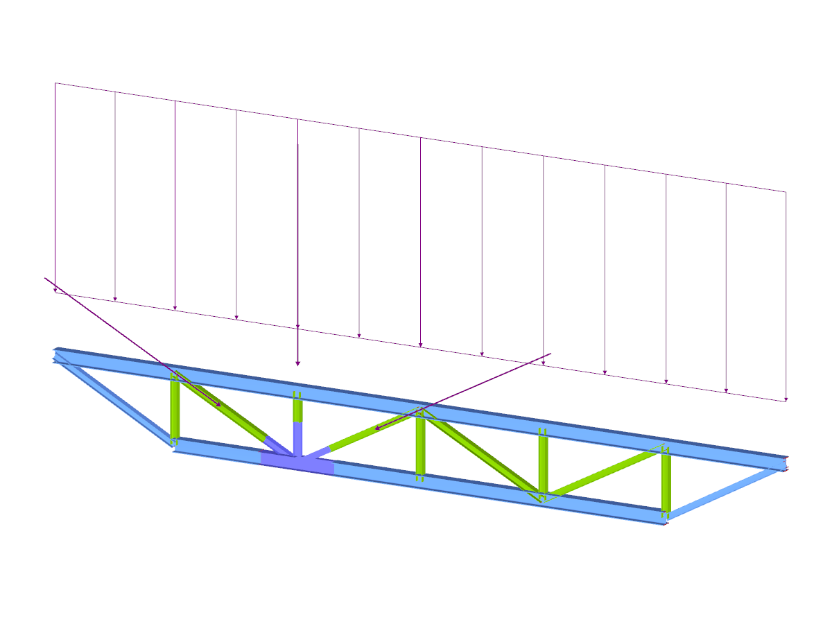
This model shows a spatial truss girder that was created as a truss structure with a closed circular cross-section. The precise geometric display in 3D format allows for detailed observations of the structural element connections. The visual rendering presents clearly defined curves and section edges, which contribute to a clear structural view. The integrated model visualization supports the analysis of complex truss components in structural design.
Model Used in
Overall
This page has 0 user ratings.
| 5 star | ||
| 4 star | ||
| 3 star | ||
| 2 star | ||
| 1 star |
Truss Girder with Circular Sections
| Number of Nodes | 48 |
| Number of Lines | 90 |
| Number of Members | 90 |
| Number of Load Cases | 2 |
| Number of Load Combinations | 2 |
| Number of Result Combinations | 1 |
| Total Weight | 1.380 t |
| Dimensions (Metric) | 14.112 x 1.813 x 1.813 m |
| Dimensions (Imperial) | 46.3 x 5.95 x 5.95 feet |
| Program Version | 5.23.02 |
You can download this structural model to use it for training purposes or for your projects. However, we do not assume any guarantee or liability for the accuracy or completeness of the model.
Related Models


Duration: 00:38:54 min
Duration: 00:00:19 min
Duration: 00:03:54 min
Duration: 00:00:48 min
Duration: 00:01:00 min

Duration: 01:06:55 min
Duration: 00:01:12 min
Duration: 00:00:22 min

Duration: 00:00:22 min


Prof._Dr.-Ing._G._Nonhoff__LI.jpg?mw=350&hash=3352d710a6bc7f4fed3f07a280a700972f70f6aa)


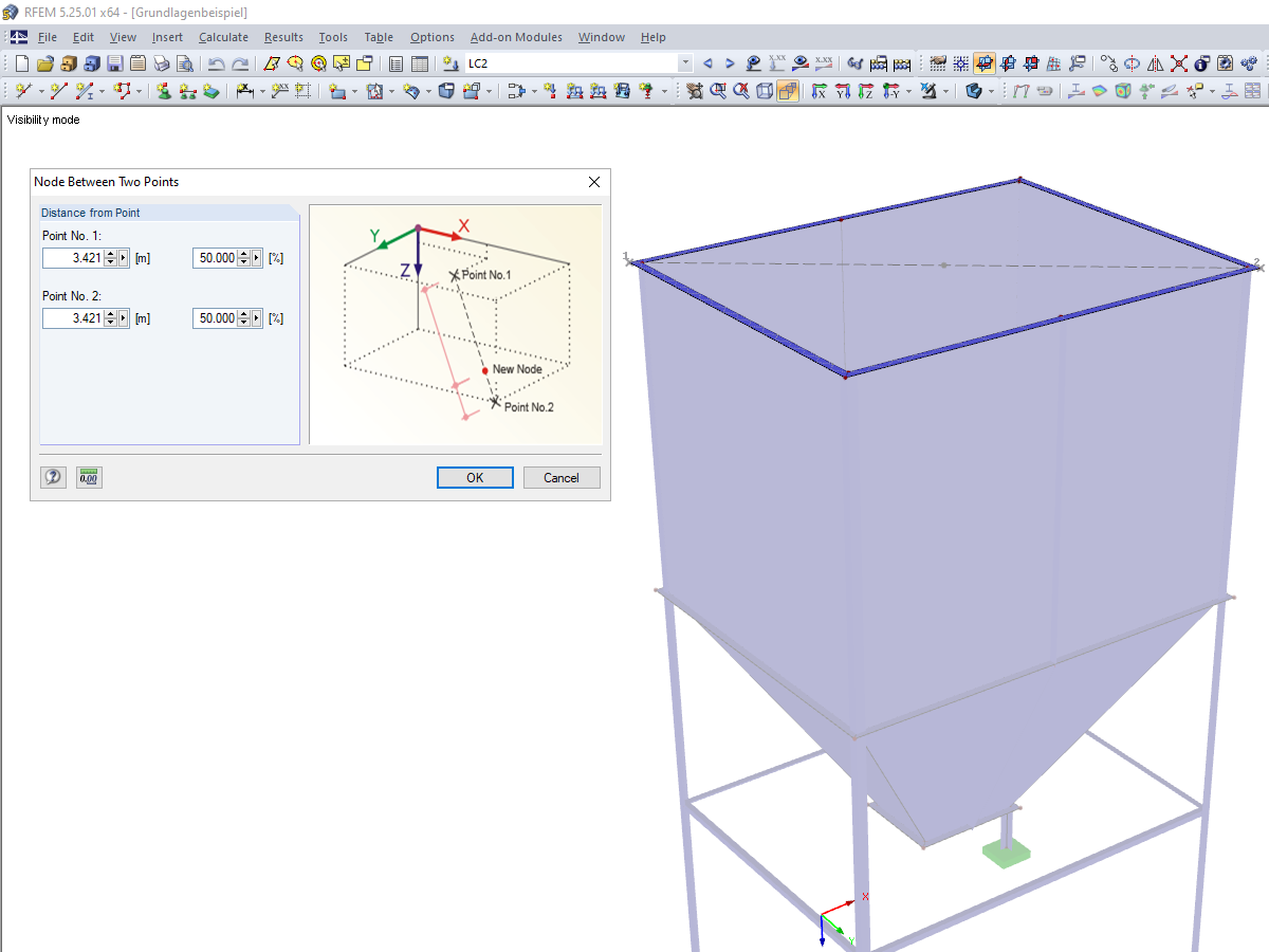
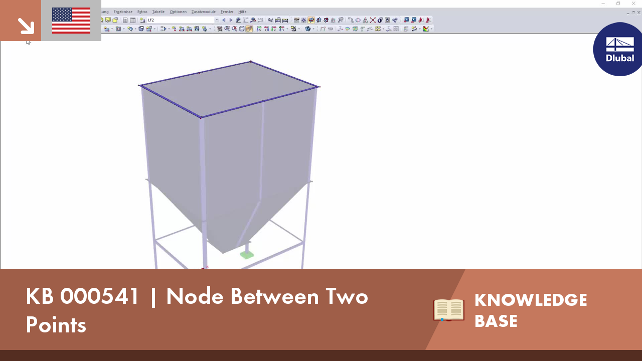
Until now, if you wanted to determine the centroid of a rectangle, it was necessary to define a line from one corner point to the diagonally opposite point. You obtained the centroid by dividing this line. In RFEM 5 and RSTAB 8, you now have the possibility to create a node between two points. Thus, it is sufficient to select the corner points; then you can determine the distance in absolute or relative values.
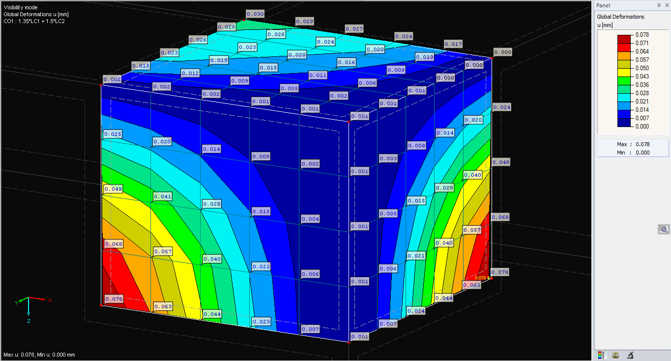
The deformations of the FE nodes are always the first result of an FE calculation. It is possible to calculate strains, internal forces, and stresses based on these deformations and the stiffness of the elements.

This article explores the importance of considering joint-structure interaction in modeling and design and how to do it in RFEM 6.
.png?mw=512&hash=4a84cbc5b1eacf1afb4217e8e43c5cb50ed8d827)
This article provides a comprehensive overview of essential seismic analysis methods, explaining their principles and applications, as well as the scenarios in which they are most effective


Want to automatically consider steel joint stiffness in your global RFEM model? Utilize the Steel Joints add-on!
Activate joint-structure interaction in the stiffness analysis of your steel joints. Hinges with springs are then automatically generated in the global model and included in subsequent calculations.

In the ultimate configuration of the steel joint design, you have the option to modify the limit plastic strain for welds.

The "Base Plate" component allows you to design base plate connections with cast-in anchors. In this case, plates, welds, anchorages, and steel-concrete interaction are analyzed.

In the "Edit Section" dialog box, you can display the buckling shapes of the Finite Strip Method (FSM) as a 3D graphic.
I want to create a mapped mesh for a circular hole plate. Is it possible to generate such a meshing in RFEM?
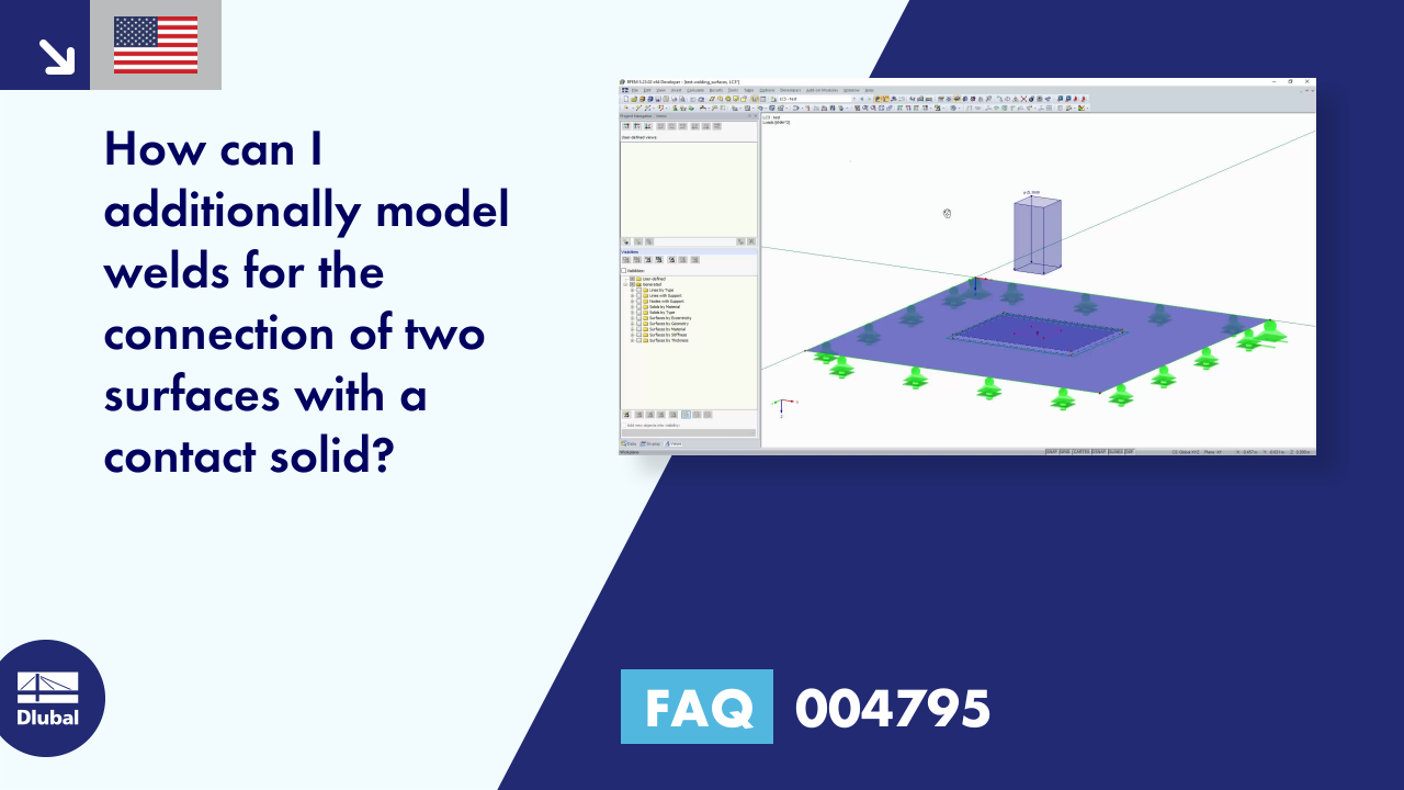
How can I additionally model welds for the connection of two surfaces with a contact solid?
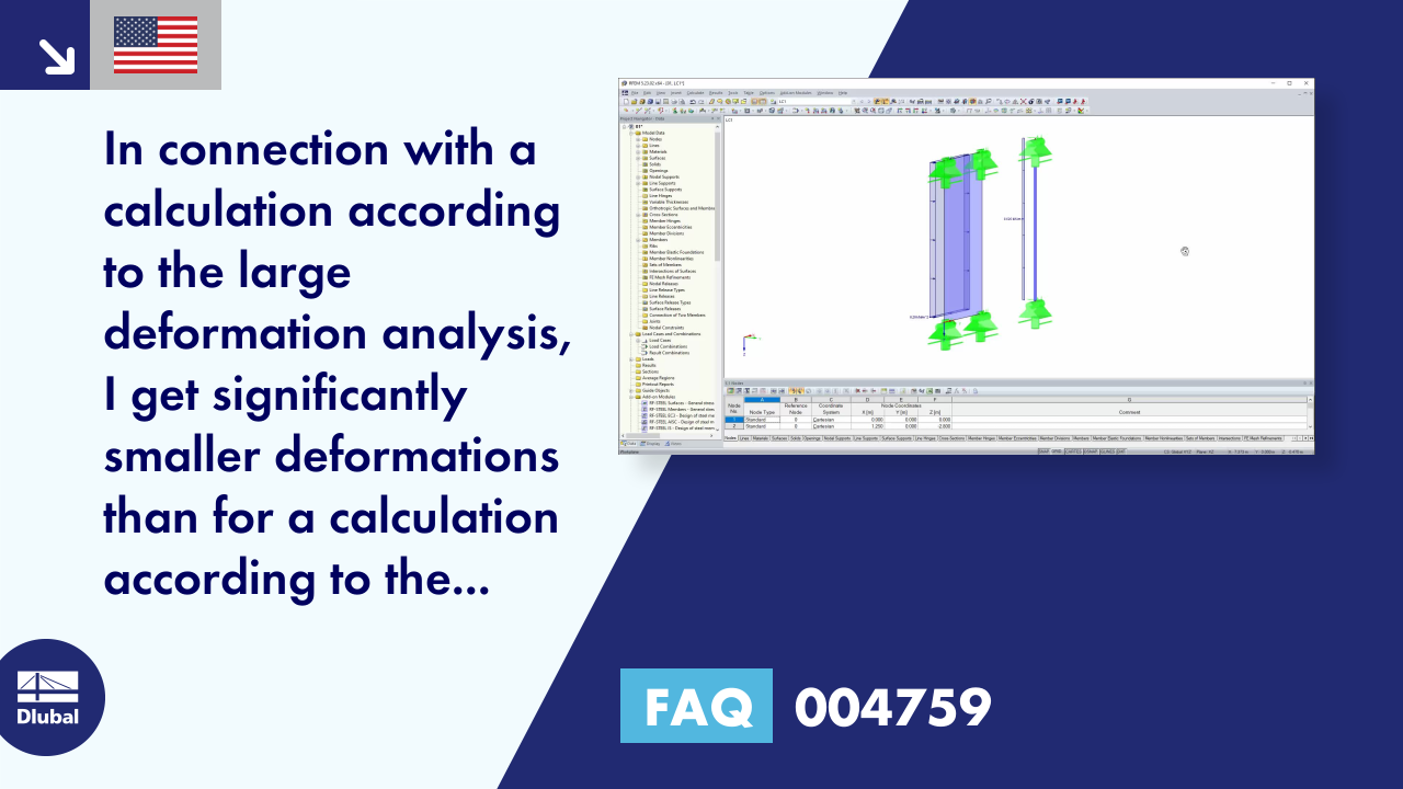
In connection with a calculation according to the large deformation analysis, I get significantly smaller deformations than for a calculation according to the linear static or second-order analysis. How can that be?
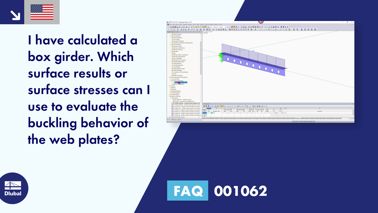
I have calculated a box girder. Which surface results or surface stresses can I use to evaluate the buckling behavior of the web plates?
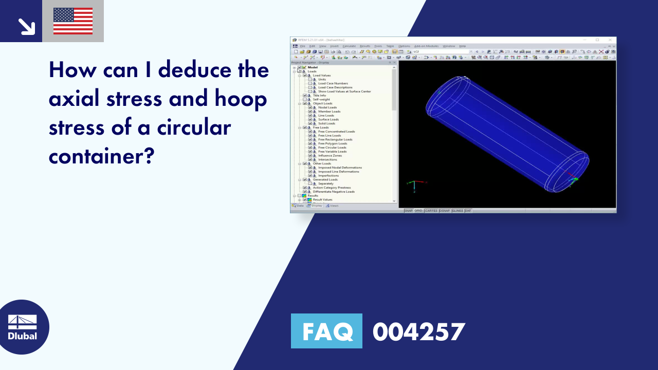
How can I deduce the axial stress and hoop stress of a circular container?
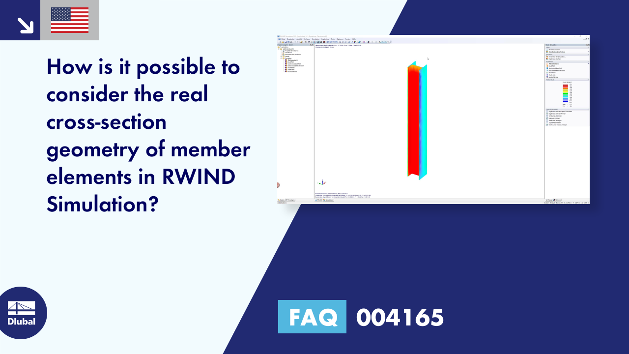
How is it possible to consider the real cross-section geometry of member elements in RWIND Simulation?


_1.jpg?mw=350&hash=ab2086621f4e50c8c8fb8f3c211a22bc246e0552)


Recommended Products for You
RFEM 6 | Main Program RFEM 6

The new generation of 3D FEA software is used for the structural analysis of members, surfaces, and solids.
Price of First License
4,790.00 USD
RFEM 6 | Design

The Steel Design add-on performs the ultimate and serviceability limit state design checks of steel members according to various standards.
Price of First License
2,970.00 USD
RFEM 6 | Joints
.png?mw=600&hash=49b6a289915d28aa461360f7308b092631b1446e)
The Steel Joints add-on for RFEM allows you to analyze steel connections using an FE model. The FE model is generated automatically in the background and can be controlled via the simple and familiar input of components.
Price of First License
2,670.00 USD
RFEM 6 | Additional Analysis

The Torsional Warping (7 DOF) add-on allows you to consider cross-section warping as an additional degree of freedom.
Price of First License
1,660.00 USD
RFEM 6 | Additional Analysis

The Nonlinear Material Behavior add-on allows you to consider material nonlinearities in RFEM for example, isotropic plastic, orthotropic plastic, isotropic damage).
Price of First License
1,660.00 USD
RFEM 6 | Additional Analysis

The Structure Stability add-on performs stability analysis of structures. It determines critical load factors and the corresponding stability modes.
Price of First License
1,460.00 USD
RFEM 6 | Additional Analysis

The Construction Stages Analysis (CSA) add-on allows for considering the construction process of structures (member, surface, and solid structures) in RFEM.
Price of First License
1,760.00 USD
RFEM 6 | Additional Analysis

The Time-Dependent Analysis (TDA) add-on allows you to consider the time-dependent material behavior of members and surfaces. The long-term effects, such as creep, shrinkage, and aging, can influence the distribution of internal forces, depending on the structure.
Price of First License
1,160.00 USD
RFEM 6 | Additional Analysis

The Form-Finding add-on finds the optimal shape of members subjected to axial forces and tension-loaded surface models. The shape is determined by the equilibrium between the member axial force or the membrane stress and the existing boundary conditions.
Price of First License
2,320.00 USD
RFEM 6 | Dynamic Analysis

The Modal Analysis add-on allows for the calculation of eigenvalues, natural frequencies, and natural periods for member, surface, and solid models.
Price of First License
1,360.00 USD
RFEM 6 | Dynamic Analysis

Using the Pushover Analysis add-on, you can analyze the seismic actions on a particular building, and thus assess whether the building can withstand an earthquake.
Price of First License
1,460.00 USD
RFEM 6 | Special Solutions

The Building Model add-on for RFEM allows you to define and manipulate a building using stories. The stories can be adjusted in many ways afterwards. The information about stories and the entire model (center of gravity) is displayed in tables and graphics.
Price of First License
1,970.00 USD
RFEM 6 | Design

The Stress-Strain Analysis add-on performs general stress analysis by calculating the existing stresses and comparing them with the limit stresses.
Price of First License
1,360.00 USD
RSTAB 9 | Main Program RSTAB 9

The modern 3D structural analysis and design program is suitable for the structural and dynamic analysis of beam structures as well as the design of concrete, steel, timber, and other materials.
Price of First License
3,380.00 USD
RSTAB 9 | Design
The Steel Design add-on performs the ultimate and serviceability limit state design checks of steel members according to various standards.
Price of First License
2,970.00 USD
RSTAB 9 | Additional Analysis
The Structure Stability add-on performs the stability analysis of structures. It determines critical load factors and the corresponding stability modes.
Price of First License
1,460.00 USD
RSTAB 9 | Design
The Stress-Strain Analysis add-on performs a general stress analysis by calculating the existing stresses and comparing them to the limit stresses.
Price of First License
1,260.00 USD
RSTAB 9 | Additional Analysis
The Torsional Warping (7 DOF) add-on allows for considering cross-section warping as an additional degree of freedom when calculating members.
Price of First License
1,660.00 USD
RSTAB 9 | Dynamic Analysis
The Modal Analysis add-on allows for the calculation of eigenvalues, natural frequencies, and natural periods for member, surface, and solid models.
Price of First License
1,360.00 USD
RSTAB 9 | Dynamic Analysis
Earthquakes may have a significant impact on the deformation behavior of buildings. A pushover analysis allows you to analyze the deformation behavior of buildings and compare them with seismic actions. Using the Pushover Analysis add-on, you can analyze the seismic actions on a particular building, and thus assess whether the building can withstand the earthquake.
Price of First License
1,460.00 USD
RFEM 6 | Dynamic Analysis

The Response Spectrum Analysis add-on performs seismic analysis using multi-modal response spectrum analysis. The spectra required for this can be created in compliance with the standards or can be user-defined. The equivalent static forces are generated from them. The add-on includes an extensive library of accelerograms from seismic zones that can be used to generate the response spectra.
Price of First License
1,560.00 USD
RFEM 6 | Special Solutions

The two-part Optimization & Costs / CO2 Emission Estimation add-on finds suitable parameters for parameterized models and blocks via the artificial intelligence (AI) technique of particle swarm optimization (PSO) for compliance with common optimization criteria. Furthermore, this add-on estimates the model costs or CO2 emissions by specifying unit costs or emissions per material definition for the structural model.
Price of First License
1,660.00 USD
RFEM 6 | Design

The Concrete Design add-on allows for various design checks according to international standards. You can design members, surfaces, and columns, as well as perform punching and deformation analyses.
Price of First License
2,970.00 USD
RSTAB 9 | Dynamic Analysis
The Response Spectrum Analysis add-on performs seismic analysis using the multi-modal response spectrum analysis. The spectra required for this can be created in compliance with the standards or can be user-defined. The equivalent static forces are generated from them. The add-on includes an extensive library of accelerograms from seismic zones that can be used to generate response spectra.
Price of First License
1,560.00 USD
RSTAB 9 | Special Solutions
The two-part Optimization & Costs / CO2 Emission Estimation add-on finds suitable parameters for parameterized models and blocks via the artificial intelligence (AI) technique of particle swarm optimization (PSO) for compliance with common optimization criteria. Furthermore, this add-on estimates the model costs or CO2 emissions by specifying unit costs or emissions per material definition for the structural model.
Price of First License
1,660.00 USD
RSTAB 9 | Design
Concrete Design add-on allows for various design checks of members and columns according to international standards.
Price of First License
2,970.00 USD