

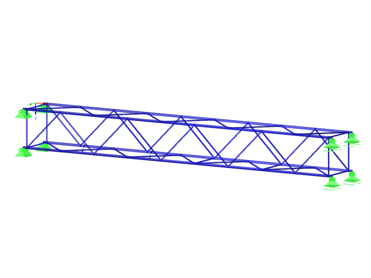
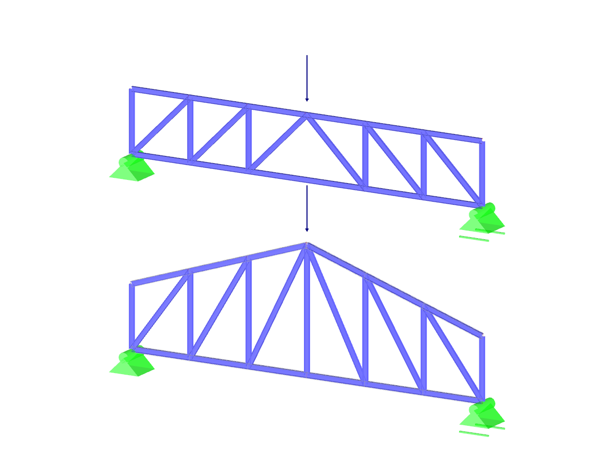
This model presents a steel truss girder in 2D where the steel connection has been innovatively modeled in 3D. The detailed display of the fasteners illustrates the complex design of steel joints. The integrated 3D model allows for realistic insights into the behavior of the connection when subjected to a load. The linked image shows the precise implementation of the structure and highlights the important details of the connection.
Overall
This page has 0 user ratings.
| 5 star | ||
| 4 star | ||
| 3 star | ||
| 2 star | ||
| 1 star |
2D Truss with 3D Steel Connection
| Number of Nodes | 149 |
| Number of Lines | 194 |
| Number of Members | 68 |
| Number of Surfaces | 32 |
| Number of Load Cases | 3 |
| Number of Load Combinations | 10 |
| Number of Result Combinations | 2 |
| Total Weight | 439,970 t |
| Dimensions (Metric) | 27.432 x 14.753 x 9.404 m |
| Dimensions (Imperial) | 90 x 48.4 x 30.85 feet |
| Program Version | 5.20.01 |
You can download this structural model to use it for training purposes or for your projects. However, we do not assume any guarantee or liability for the accuracy or completeness of the model.
Related Models


Duration: 00:02:14 min
Duration: 00:02:32 min

Duration: 00:01:47 min

Duration: 01:09:52 min

Duration: 01:13:10 min

Duration: 01:05:10 min

Duration: 00:43:11 min

Duration: 01:02:19 min
Duration: 00:01:11 min


![Basic Shapes of Membrane Structures [1]](/en/webimage/009595/2419502/01-en-png-png.png?mw=512&hash=6ca63b32e8ca5da057de21c4f204d41103e6fe20)
This paper is focused on the specific aspects of designing membrane structures that have specific requirements, such as form-finding and cutting pattern generation. An integral part of the design of these structures is the process of finding suitable prestressed shapes and generating cutting patterns. The text briefly describes two basic processes in the design of membrane structures. The physical principles are explained and the individual theses illustrated by examples.
RFEM and RSTAB are able to cover a large number of branches in the building and construction industry with their generally usable structural frame analysis and FEM programs. Designing cable structures is thus also possible in both software solutions. Some assistance tools for modeling and design will be presented in the following text.

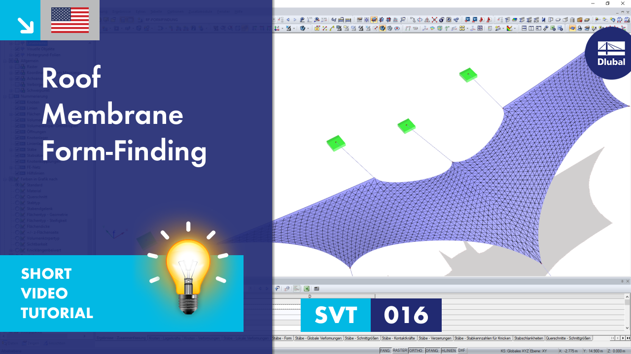
The RF-FORM-FINDING add-on module determines equilibrium shapes of membrane and cable elements in RFEM. In this calculation process, the program searches for a geometric position for the membrane and cable elements in which their surface stress/prestress is in equilibrium with the natural and geometric boundary conditions. This process is called form-finding (hereinafter referred to as FF).

The form-finding process in RF-FORM-FINDING displaces the corner nodes of FE elements of a membrane surface in space until the defined surface stress is in equilibrium with the boundary conditions. This displacement is independent of the element geometry. In the case of elements with four corner nodes, the free displacement may cause spatial drilling in the element plane and thus exceed the validity limits of the calculation; therefore, triangular elements are generally recommended for form‑finding systems. Triangular elements remain independent of the corner node displacement and stay within the calculation limitations.


- Planar and geodesic cutting lines
- Flattening of double-curved surface parts of tensioned membranes or pneumatic cushions
- Definition of cutting patterns by using boundary lines which are not required to be connected
- Sophisticated flattening based on the minimum energy theory
- Welding and boundary allowances
- Uniform or linear compensation in warp and weft direction
- Possibility of different compensations for boundary lines
- Adaptable data organisation (any additional modification of input data is considered up to the final "weld")
- Graphical display of cutting patterns
- Statistical information about each cutting pattern (width, length, size)
- Option to automatically generate cutting patterns from cells

RF-CUTTING-PATTERN is activated by selecting the respective option in the Options tab in General Data of any RFEM model. After activating the add‑on module, a new object, "Cutting Patterns", is displayed under Model Data. If the membrane surface distribution for cutting in the basic position is too large, you can divide the surface by cutting lines (line types "Cut via Two Lines" or "Cut via Section") in the corresponding partial strips.
Then you can define the individual entries for each cutting pattern using the "Cutting Pattern" object. Here you can set boundary lines, compensations, and allowances.
Steps of the working sequence:
- Creation of cutting lines
- Creation of the pattern by selecting its boundary lines or using a semi‑automatic generator
- Free selection of warp and weft orientation by entering an angle
- Application of compensation values
- Optional definition of different compensations for boundary lines
- Different allowances (welding, boundary line)
- Preliminary representation of the cutting pattern in the graphic window at the side without starting the main nonlinear calculation

The nonlinear calculation adopts the real mesh geometry of planar, buckled, simple curved, or double curved surface components from the selected cutting pattern and flattens this surface component in compliance with the minimization of distortion energy, assuming defined material behavior.
In simplified terms, this method attempts to compress the mesh geometry in a press, assuming frictionless contact, and to find the state in which the stresses from flattening in the component are in equilibrium in the plane. This way, minimum energy and optimum accuracy of the cutting pattern are achieved. Compensation for warp and weft as well as compensation for boundary lines are considered. Then, the defined allowances on boundary lines are applied to the resulting planar surface geometry.
Features:
- Minimization of distortion energy in the flattening process for very accurate cutting patterns
- Application for almost all mesh arrangements
- Recognition of adjacent cutting pattern definitions to keep the same length
- Mesh application for main calculation

After the calculation, the "Point Coordinates" tab appears in the cutting pattern dialog box. In this tab, the result is displayed in the form of a table with coordinates and a surface in the graphical window. The coordinate table presents new flattened coordinates relative to the centroid of the cutting pattern for each mesh node. Furthermore, the cutting pattern with the coordinate system at the centroid is represented in the graphical window. When selecting a table cell, the respective node is displayed with an arrow in the graphic. In addition, the area of the cutting pattern is displayed below the node table.
Moreover, standard stress/strain results for each pattern are displayed in the RF‑CUTTING‑PATTERN load case in RFEM.
Features:
- Results in a table, including information about the cutting pattern
- Smart table relating to the graphic
- Results of flattened geometry in a DXF file
- Output of strains after flattening in order to evaluate the cutting patterns
- Results of strains after flattening for the evaluation of patterns
How does RFEM efficiently determine the shape of a curved plate structure (compression shell) subjected to compression only?
I cannot define the prestress separately for warp and weft in RF‑FORM‑FINDING. How can I activate it?
How do I activate form-finding of a membrane surface?
How is it possible to avoid singularities on membrane surfaces due to form-finding?
Why is the compensated cutting pattern length of a membrane surface incompatible with the defined compensation?
How are guy wires processed in RF‑FORM‑FINDING, concerning the prestress load to be applied? Is it necessary to assign a prestressing force to the guy wires?


