
Dlubal_KohlA.png?mw=926&hash=9f9bb7eb9fbef0f103fa5ec5995f88c383088be3)
The model shows a modern parking garage, designed as a concrete and solid structure. The focus is on a functionally designed parking level that defines central traffic and usage areas. The structural details allow for insights into practical structural implementations and show precise calculations. The linked image visualizes the clear design and realism of the parking garage.
Model Used in
Overall
This page has 0 user ratings.
| 5 star | ||
| 4 star | ||
| 3 star | ||
| 2 star | ||
| 1 star |
Concrete Parking Garage
| Number of Nodes | 225 |
| Number of Lines | 220 |
| Number of Members | 78 |
| Number of Surfaces | 27 |
| Number of Load Cases | 4 |
| Number of Load Combinations | 8 |
| Number of Result Combinations | 1 |
| Total Weight | 1636,969 t |
| Dimensions (Metric) | 40.850 x 18.250 x 9.250 m |
| Dimensions (Imperial) | 134.02 x 59.88 x 30.35 feet |
| Program Version | 5.21.02 |
You can download this structural model to use it for training purposes or for your projects. However, we do not assume any guarantee or liability for the accuracy or completeness of the model.


Duration: 00:00:23 min
Duration: 00:00:48 min
Duration: 00:00:55 min
Duration: 00:00:40 min
Duration: 00:00:11 min

Duration: 00:00:06 min

Duration: 00:01:42 min
Duration: 00:01:33 min
Duration: 00:00:48 min


.png?mw=350&hash=f79867dbf405d536638daef39ee25b113e6e540d)


Validating CFD simulations with experimental data enhances accuracy by comparing simulation outcomes with real-world conditions. This process identifies discrepancies, allowing adjustments to enhance model reliability. Ultimately, it builds confidence in the simulation's ability to predict wind load scenarios.
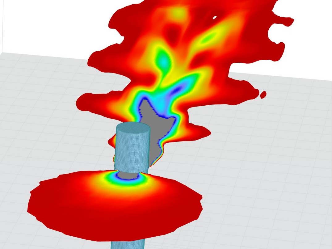
Modeling a Kármán vortex street in RWIND

In RFEM 6 it is possible to save selected objects (as well as whole structures) as blocks and reuse them in other models. Three types of blocks can be distinguished: non-parameterized, parameterized, and dynamic blocks (via JavaScript). This article will focus on the first block type (non-parameterized).
This article describes how to create a user-defined antenna bracket to be used in RF-/TOWER Equipment.


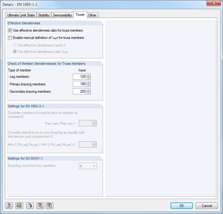
After generating the effective lengths, the results are displayed in clearly arranged tables. You can modify the effective lengths manually there.
The Export function transfers the effective lengths to the RF-/TOWER Design add-on module for further calculation. The complete module data are part of the RFEM/RSTAB printout report. The report contents and the extent of the results can be selected specifically for the individual designs.

Finally, it is possible to export the generated model to RFEM/RSTAB with a single mouse click.
The complete module data are part of the RFEM/RSTAB printout report. The report contents and the extent of the results can be selected specifically for the individual designs.
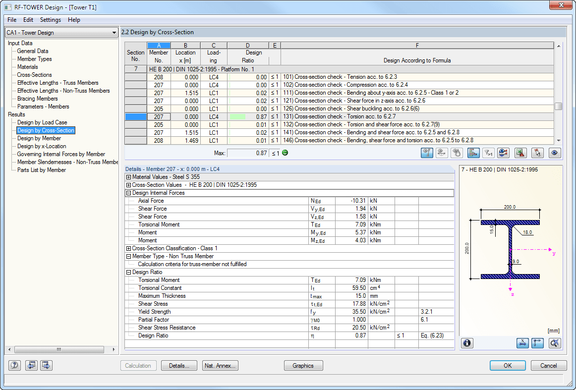
The results are displayed in clearly arranged module windows. In addition to the design data, the results include all design-relevant parameters. A parts list is generated automatically during the calculation.
The complete module data are part of the RFEM/RSTAB printout report. The report contents and the extent of the results can be selected specifically for the individual designs.
When performing the design of tension, compression, bending, and shear loading, the module compares the design values of the maximum load capacity to the design values of the actions. If the components are subjected to both bending and compression, the program performs an interaction. You can determine the factors according to Method 1 (Annex A) or Method 2 (Annex B).
The flexural buckling design requires neither the slenderness nor the elastic critical buckling load of the governing buckling case. The module automatically calculates all required factors for the bending stress design value. RF-/TOWER Design determines the effective critical moment for lateral-torsional buckling for each member on every x-location of the cross-section.
How can I find RWIND results such as forces data in ParaView?
How can I obtain wind force coefficient in RWIND?
Is it possible to consider the eccentricity of unsymmetrical line welds for the stress analysis in RFEM 6?
Has the RF-TOWER add-on module for RFEM 5 already been added to RFEM 6?
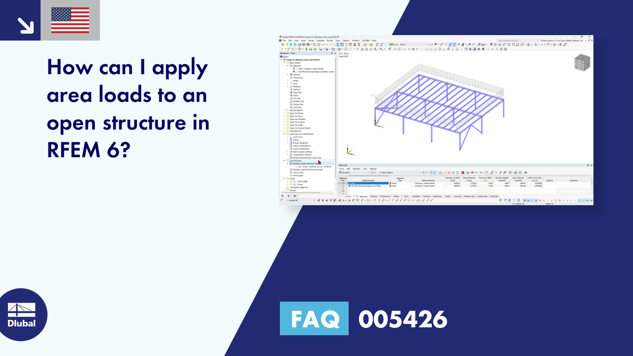
How can I apply area loads to an open structure in RFEM 6?
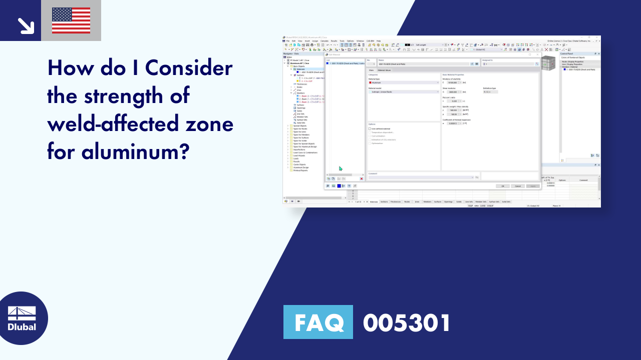
How do I consider the strength of weld-affected zone for aluminum?


Recommended Products for You
RFEM 6 | Main Program RFEM 6

The new generation of 3D FEA software is used for the structural analysis of members, surfaces, and solids.
Price of First License
4,790.00 USD
RFEM 6 | Design

The Steel Design add-on performs the ultimate and serviceability limit state design checks of steel members according to various standards.
Price of First License
2,970.00 USD
RFEM 6 | Joints
.png?mw=600&hash=49b6a289915d28aa461360f7308b092631b1446e)
The Steel Joints add-on for RFEM allows you to analyze steel connections using an FE model. The FE model is generated automatically in the background and can be controlled via the simple and familiar input of components.
Price of First License
2,670.00 USD
RFEM 6 | Additional Analysis

The Structure Stability add-on performs stability analysis of structures. It determines critical load factors and the corresponding stability modes.
Price of First License
1,460.00 USD
RFEM 6 | Design

The Stress-Strain Analysis add-on performs general stress analysis by calculating the existing stresses and comparing them with the limit stresses.
Price of First License
1,360.00 USD
RFEM 6 | Special Solutions

The two-part Optimization & Costs / CO2 Emission Estimation add-on finds suitable parameters for parameterized models and blocks via the artificial intelligence (AI) technique of particle swarm optimization (PSO) for compliance with common optimization criteria. Furthermore, this add-on estimates the model costs or CO2 emissions by specifying unit costs or emissions per material definition for the structural model.
Price of First License
1,660.00 USD
RSTAB 9 | Main Program RSTAB 9

The modern 3D structural analysis and design program is suitable for the structural and dynamic analysis of beam structures as well as the design of concrete, steel, timber, and other materials.
Price of First License
3,380.00 USD
RSTAB 9 | Design
The Steel Design add-on performs the ultimate and serviceability limit state design checks of steel members according to various standards.
Price of First License
2,970.00 USD
RSTAB 9 | Additional Analysis
The Structure Stability add-on performs the stability analysis of structures. It determines critical load factors and the corresponding stability modes.
Price of First License
1,460.00 USD
RSTAB 9 | Design
The Stress-Strain Analysis add-on performs a general stress analysis by calculating the existing stresses and comparing them to the limit stresses.
Price of First License
1,260.00 USD
RSTAB 9 | Special Solutions
The two-part Optimization & Costs / CO2 Emission Estimation add-on finds suitable parameters for parameterized models and blocks via the artificial intelligence (AI) technique of particle swarm optimization (PSO) for compliance with common optimization criteria. Furthermore, this add-on estimates the model costs or CO2 emissions by specifying unit costs or emissions per material definition for the structural model.
Price of First License
1,660.00 USD
RSECTION 1 | Cross-Section Properties

The stand-alone program RSECTION determines the section properties for any thin-walled and massive cross-sections.
Price of First License
1,970.00 USD
RFEM 5 | Main Program RFEM

Structural engineering software for a finite element analysis (FEA) of planar and spatial structural systems consisting of plates, walls, shells, members (beams), solids, and contact elements
Price of First License
4,690.00 USD
RFEM 5 | Steel and Aluminum Structures

Plastic design of cross-sections according to the Partial Internal Forces Method (PIFM) and Simplex Method
Price of First License
1,110.00 USD
RFEM 5 | Steel and Aluminum Structures

Fatigue design of members and sets of members according to EN 1993-1-9
Price of First License
1,460.00 USD
RFEM 5 | Towers and Masts

Generation of geometrically complex 3D tower structures, such as lattice towers and radio masts
Price of First License
2,220.00 USD
RFEM 5 | Towers and Masts

Generation of the equipment for lattice towers of mobile operators
Price of First License
1,310.00 USD
RFEM 5 | Towers and Masts

Generation of the wind, ice, and variable loads for lattice towers
Price of First License
2,220.00 USD
RFEM 5 | Towers and Masts

Determination of effective lengths for lattice towers
Price of First License
760.00 USD
RFEM 5 | Towers and Masts

Design of triangular and quadrilateral lattice towers according to the European standards
Price of First License
1,970.00 USD
RFEM 5 | Connections

Design of nominally pinned bolted connections of members used in lattice towers according to Eurocode 3
Price of First License
860.00 USD
RSTAB 8 | Main Program RSTAB

Structural engineering software for design of frame, beam, and truss structures, as well as for linear and nonlinear calculations of internal forces, deformations, and support reactions
Price of First License
3,280.00 USD
RSTAB 8 | Steel and Aluminum Structures

Fatigue design of members and sets of members according to EN 1993-1-9
Price of First License
1,260.00 USD
RSTAB 8 | Steel and Aluminum Structures

Plastic design of cross-sections according the Partial Internal Forces Method (PIFM) and Simplex Method
Price of First License
960.00 USD
RSTAB 8 | Towers and Masts

Generation of geometrically complex 3D tower structures, such as lattice towers and radio masts
Price of First License
1,970.00 USD
RSTAB 8 | Towers and Masts

Generation of equipment for lattice towers of mobile operators
Price of First License
1,110.00 USD
RSTAB 8 | Towers and Masts

Generation of wind, ice, and variable loads for lattice towers
Price of First License
1,970.00 USD
RSTAB 8 | Towers and Masts

Determination of effective lengths for lattice towers
Price of First License
660.00 USD
RSTAB 8 | Towers and Masts

Design of triangular and quadrilateral lattice towers according to the European standards
Price of First License
1,660.00 USD
RSTAB 8 | Connections

Design of nominally pinned bolted connections of members used in lattice towers according to Eurocode 3
Price of First License
760.00 USD
RFEM 6 | Additional Analysis

The Nonlinear Material Behavior add-on allows you to consider material nonlinearities in RFEM for example, isotropic plastic, orthotropic plastic, isotropic damage).
Price of First License
1,660.00 USD
RFEM 6 | Additional Analysis

The Torsional Warping (7 DOF) add-on allows you to consider cross-section warping as an additional degree of freedom.
Price of First License
1,660.00 USD
RFEM 6 | Special Solutions

The Multilayer Surfaces add-on allows you to define multilayer surface structures. The calculation can be carried out with or without the shear coupling.
Price of First License
1,560.00 USD
RFEM 6 | Design

The Concrete Design add-on allows for various design checks according to international standards. You can design members, surfaces, and columns, as well as perform punching and deformation analyses.
Price of First License
2,970.00 USD
RFEM 6 | Design

The Timber Design add-on performs the ultimate, serviceability, and fire resistance limit state design checks of timber members according to various standards.
Price of First License
2,170.00 USD
RFEM 6 | Design

The Masonry Design add-on for RFEM allows you to design masonry using the finite element method. It was developed as part of the research project titled DDMaS – Digitizing the Design of Masonry Structures. The material model represents the nonlinear behavior of the brick-mortar combination in the form of macro-modeling.
Price of First License
1,860.00 USD
RFEM 6 | Design

The Aluminum Design add-on performs the ultimate and serviceability limit state design checks of aluminum members according to various standards.
Price of First License
1,970.00 USD
RSTAB 9 | Additional Analysis
The Torsional Warping (7 DOF) add-on allows for considering cross-section warping as an additional degree of freedom when calculating members.
Price of First License
1,660.00 USD
RSTAB 9 | Design
Concrete Design add-on allows for various design checks of members and columns according to international standards.
Price of First License
2,970.00 USD
RSTAB 9 | Design
The Timber Design add-on performs the ultimate, serviceability, and fire resistance limit state design checks of timber members according to various standards.
Price of First License
2,170.00 USD
RSTAB 9 | Design
The Aluminum Design add-on performs the ultimate and serviceability limit state design checks of aluminum members according to various standards.
Price of First License
1,970.00 USD
RFEM 6 | Additional Analysis

The Construction Stages Analysis (CSA) add-on allows for considering the construction process of structures (member, surface, and solid structures) in RFEM.
Price of First License
1,760.00 USD