

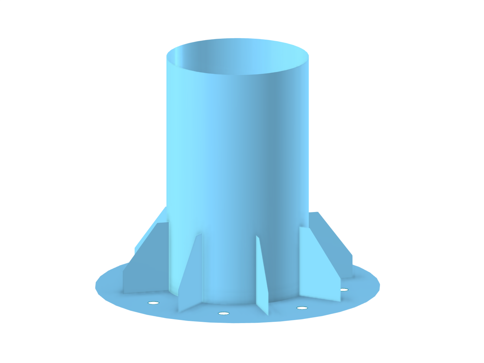
This model shows an innovative approach to displaying steel nodes using combined solid elements whose final form is defined by Boolean operations. It illustrates how several individual solids merge into a complex structural component in order to model realistic steel joints. The application of this method simplifies the simulation of connection principles in steel structures. The linked image presents a clear, three-dimensional visualization of the model and highlights the precise modeling of complex solid boundaries.
Overall
This page has 0 user ratings.
| 5 star | ||
| 4 star | ||
| 3 star | ||
| 2 star | ||
| 1 star |
Solid Model of Steel Node
| Number of Nodes | 60 |
| Number of Lines | 28 |
| Number of Surfaces | 37 |
| Number of Solids | 9 |
| Number of Load Cases | 1 |
| Total Weight | 0,529 t |
| Dimensions (Metric) | 0.917 x 0.848 x 0.651 m |
| Dimensions (Imperial) | 3.01 x 2.78 x 2.14 feet |
| Program Version | 5.23.00 |
You can download this structural model to use it for training purposes or for your projects. However, we do not assume any guarantee or liability for the accuracy or completeness of the model.
Related Models
.png)

Duration: 00:00:50 min

Duration: 00:00:40 min

Duration: 00:00:56 min

Duration: 00:00:11 min

Duration: 01:19:08 min

Duration: 01:06:17 min
.png?mw=350&hash=c6c25b135ffd26af9cd48d77813d2ba5853f936c)
Duration: 00:08:02 min

Duration: 00:00:21 min
Duration: 00:01:00 min


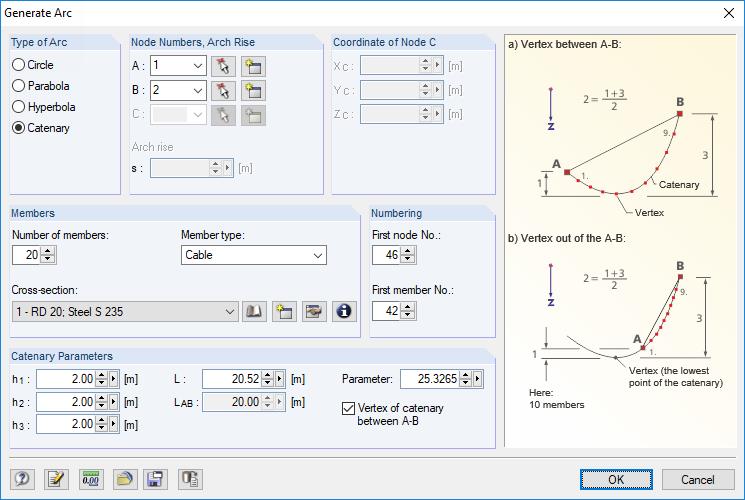
RFEM and RSTAB are able to cover a large number of branches in the building and construction industry with their generally usable structural frame analysis and FEM programs. Designing cable structures is thus also possible in both software solutions. Some assistance tools for modeling and design will be presented in the following text.
![Basic Shapes of Membrane Structures [1]](/en/webimage/009595/2419502/01-en-png-png.png?mw=512&hash=6ca63b32e8ca5da057de21c4f204d41103e6fe20)
This paper is focused on the specific aspects of designing membrane structures that have specific requirements, such as form-finding and cutting pattern generation. An integral part of the design of these structures is the process of finding suitable prestressed shapes and generating cutting patterns. The text briefly describes two basic processes in the design of membrane structures. The physical principles are explained and the individual theses illustrated by examples.

This article describes and explains the influence of bending stiffness of cables on their internal forces. Furthermore, the text provides information on how this influence can be reduced.
Using the Timber Design add-on, timber column design is possible according to the 2018 NDS standard ASD method. Accurately calculating timber member compressive capacity and adjustment factors is important for safety considerations and design. The following article will verify the maximum critical buckling strength calculated by the Timber Design add-on using step-by-step analytical equations as per the NDS 2018 standard including the compressive adjustment factors, adjusted compressive design value, and final design ratio.


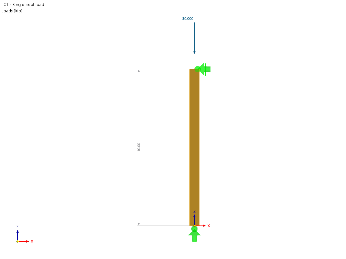
For design objects, you can optionally display sags or extreme results.
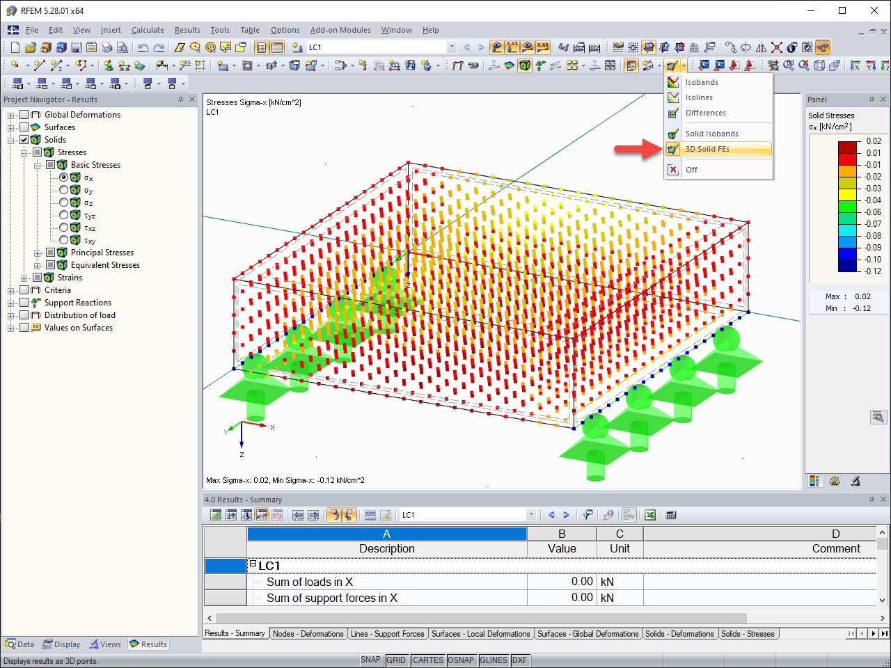
The results of solid stresses can be displayed as colored 3D points in the finite elements.
.png?mw=512&hash=ea9bf0ab53a4fb0da5c4ed81d32d53360ab2820c)
The number of degrees of freedom in a node is no longer a global calculation parameter in RFEM (6 degrees of freedom for each mesh node in 3D models, 7 degrees of freedom for the warping torsion analysis). Thus, each node is generally considered with a different number of degrees of freedom, which leads to a variable number of equations in the calculation.
This modification speeds up the calculation, especially for models where a significant reduction of the system could be achieved (for example, trusses and membrane structures).

Display extended strains of members, surfaces, and solids (for example, the important principal strains, equivalent total strains, and so on) in the Project Navigator - Results in RFEM as well as in Table 4.0.
For example, you can display governing plastic strains when performing the plastic design of connections with surface elements.
I divided a member by several nodes. When applying the imperfections, each partial member is now assigned its own imperfection.
How can I define an imperfection over all partial members?
How do I manually enter a precamber to a member as an imperfection?
I have problems when defining equivalent imperfections in RFEM/RSTAB. What should I do?
Where can I find the update reports for RFEM 5, RSTAB 8, SHAPE-THIN, SHAPE-MASSIVE, RX-TIMBER, CRANEWAY, PLATE-BUCKLING, COMPOSITE-BEAM?
For my NVIDIA graphics card, I need to select between a driver from the "Production Branch" and a "New Feature Branch." Which driver is best suited for RFEM/RSTAB?
Is it possible to quickly evaluate whether the mesh used is fine enough?

_1.jpg?mw=350&hash=ab2086621f4e50c8c8fb8f3c211a22bc246e0552)


