For a structural analysis, you define loads in load cases, combine them, and run the calculation. A dynamic analysis, however, is based on masses. You do not need to define any masses for this tutorial, though: all existing loads can be imported and used for the modal analysis.
Defining the Load Case
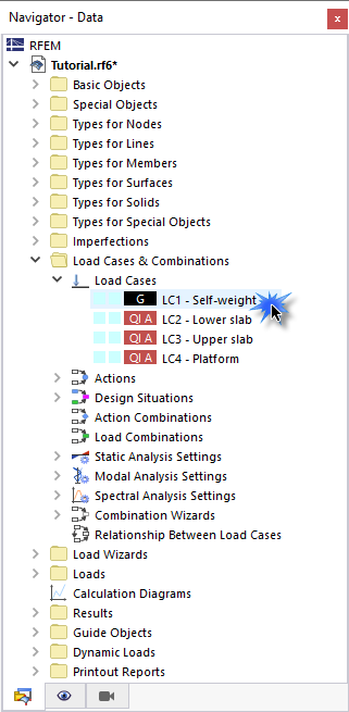
To create a new load case for the modal analysis, go to the Load Cases & Combinations folder in the navigator, open the Load Cases subentry and double-click one of the four load cases, such as LC1 - Self-weight.
In the 'Load Cases & Combinations' dialog box, click the
![]() button in the bottom-left corner (1).
button in the bottom-left corner (1).
In the 'Load Case Name' area, enter Modal analysis (2). Then select the Modal Analysis option from the 'Analysis type' list (3). This setting controls that a dynamic analysis is to be applied to the load case.
As mentioned above, existing loads can be imported as masses. If only the self-weight masses were considered for the modal analysis of the model, it would not be correct. The live load masses must be taken into account as well. As dynamic analyses follow specific rules when combining load cases, a new design situation must be created. Go to the Design Situations tab (1). Click the
![]() button in the bottom-left corner (2).
button in the bottom-left corner (2).
The new design situation DS5 is created. Select the Seismic/Mass combination - psi,E,i option from the 'Design situation type' list (3). When you click on the
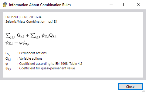
![]() button (4), you can check the criteria for seismic combinations according to EN 1990 in the 'Information About Combination Rules' dialog box.
button (4), you can check the criteria for seismic combinations according to EN 1990 in the 'Information About Combination Rules' dialog box.
Click Close and go on to the Action Combinations tab.
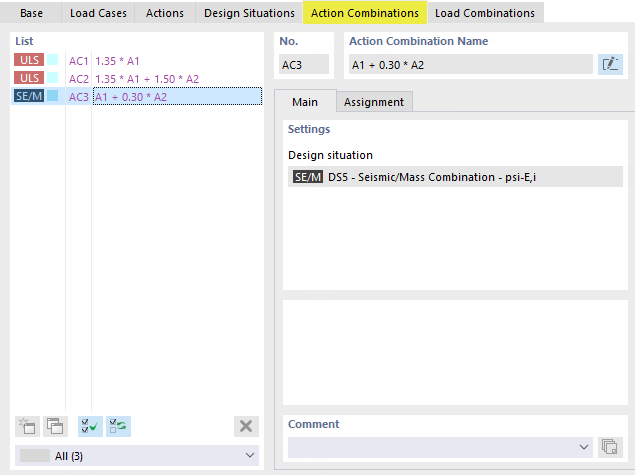
The seismic actions are combined in action combination AC3 where the ψ factor of 0.30 is applied for imposed loads.
When you select the Load Combinations tab next, the program creates the seismic combination CO9. Select it. To check how the four load cases are each taken into account, select the Assignment subtab.
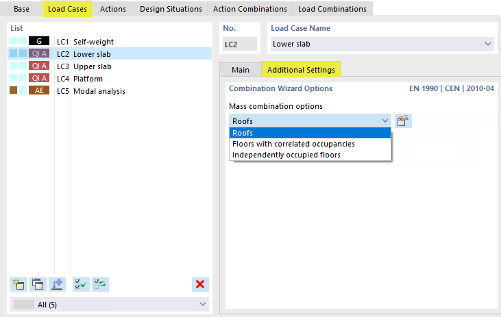
Go back to the Load Cases tab. Select LC2 in the list and go to the Additional Settings subtab. Make sure that the Roofs option is set for the combination of masses. For floors, different combination rules would be relevant.
Click through the load cases LC3 and LC4 to check whether the mass combination settings are identical.
Finally select the modal analysis load case LC5.
Open the 'Import masses only from load case/load combination' list where you select the last option: CO9 - LC1 + 0.30*LC2 + 0.30*LC3 + 0.30*LC4. Thus, all load types such as forces and moments of the four load cases will be converted to masses with the relevant ψ factors and by applying the mass conversion constant as defined in the Settings & Options of the model base data.
Calculating the Load Case
Click Calculate to perform the modal analysis of LC5 with the default analysis settings. As soon as the calculation is done, the mode shapes of the model are displayed in the work window. Four modes are listed in the 'Natural frequencies' table.
You can switch among the mode shapes (displacements) belonging to the four natural frequencies by using the
![]() and
and
![]() buttons in the 'Navigator - Results'. When you do so, you will notice that mostly local shapes of the platform beams occur.
buttons in the 'Navigator - Results'. When you do so, you will notice that mostly local shapes of the platform beams occur.
Select the Effective Modal Masses table. When you check the factors for the effective modal masses, the results in the fmeX and fmeY columns show that practically no modal masses are associated to the first four natural frequencies.
As the mass of the platform is small compared to the total mass, its mode shapes are more or less irrelevant for the seismic forces. To get reliable results, it is necessary to capture the global mode shapes, not the local effects. The Eurocode standard also requires that the sum of the effective modal masses for the modes taken into account must be at least 90% of the total mass (see [1] 4.3.3.3.1). Therefore, it is necessary to adjust the settings for the modal analysis.





.png?mw=350&hash=c6c25b135ffd26af9cd48d77813d2ba5853f936c)


.png?mw=512&hash=4a84cbc5b1eacf1afb4217e8e43c5cb50ed8d827)




_1.jpg?mw=350&hash=ab2086621f4e50c8c8fb8f3c211a22bc246e0552)


