


The walls of one or more stories can be combined to form shear walls. For each of these shear walls, RFEM creates a result member , which converts the surface internal forces into member internal forces by an integration. This way, you can evaluate the forces in each shear wall and also design the shear walls as members; for example, in the case of concrete or timber materials.
To define a shear wall, right-click the Shear Walls entry in the "Building Model" category. In the shortcut menu, select New Shear Wall.
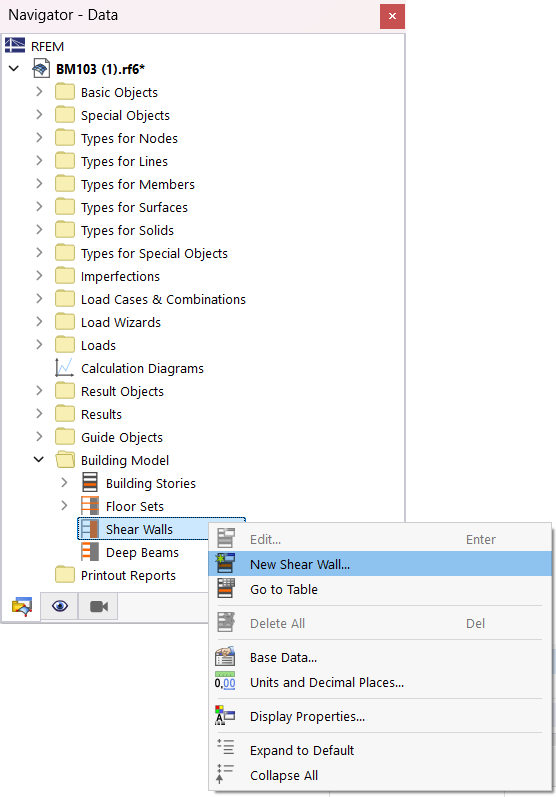
In the "Shear Walls" dialog box, you can then define the properties of the story walls.

Assignable Objects
You can describe a shear wall using surfaces and surface cells, or members. Select the appropriate option from the list (see the image above).
Surfaces and Surface Cells / Members
Select surfaces and surface cells or members graphically in the model using the
![]() button. The numbers of the objects cannot be entered manually.
button. The numbers of the objects cannot be entered manually.
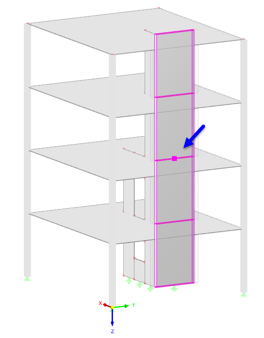
The shear walls do not need to be in one plane; they can also have spatial shapes.

If the stories have irregular geometries, it is possible to divide the surfaces by internal lines and generate surface cells. You can then assign them accordingly. This way, you can avoid distorted results or problems in the design (for example, rebars in openings).

Segments
If the objects are defined correctly, the program creates a "segment" for each story, with a result member integrating the internal forces of the surfaces, surface cells, or members.
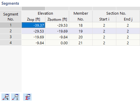
The table lists the coordinates of each floor, the numbers of the generated result beams, and the associated cross-sections.
Using the buttons below the table, you can check the properties of the generated member sets
![]() , members
, members
![]() and cross-sections
and cross-sections
![]() . It is not possible to edit the objects.
. It is not possible to edit the objects.
Information
In this section, you can find specific information about the current shear wall. The first column of values lists the analytical information; the second column includes the information based on the generated FE mesh.
The center of gravity of a shear wall is also displayed in the model.
Options
The "Generate Result Sections" option allows you to create horizontal sections in the shear wall. If you select the check box, several result sections will be generated. In the "Information" dialog section, you can see the amount and numbers of these sections. For each story height, two sections are created, once determining the results of the wall surface above, and once that of the wall surface below.
You can evaluate the results in the sections on the model as usual.
Section
For each segment of the wall, the program creates an equivalent cross-section and assigns it to the result beam. The member cross-section corresponds to the surface thickness and the width of the segment. Usually, this creates in a massive rectangular cross-section with the "R_M1" section type.

In the case of shear walls that do not rest in one plane, a corresponding RSECTION cross-section is created (see the image Shear Wall Over Two Stories with Two Result Members).
Design Properties
You can design the internal forces of the shear wall result member using member design in some design add-ons; for example, in the course of the concrete or timber design. To do this, select the Design Properties check box in the corresponding section.

Thus, several tabs are added to the dialog box where you can specify the settings for the design.

In the ultimate configurations of Concrete Design, it is possible to apply special design rules for the vertical and horizontal reinforcement of shear walls (see the chapter Deep Beams).