Corrugated web beams allow for further optimization of steel structures. They are often used to reduce the self-weight of main load-bearing elements and to prevent buckling failure of webs due to the corrugation.
This example will be based on a WTA – 1250 – 300x20 Beam from the Zeman catalogue.
To create a model of this beam, it's best to start by modeling a sine wave that will be used to edit the web. This consists of the steps shown below and in the attached images.
- Create nodes representing sine function.
- Copy nodes to desired length of beam.
- In RFEM's Lines table, manually create spline from 1st to last node.
After these steps, it's recommended to create a parametric section with the dimensions of the corrugated beam. Members using this section can later be transformed into surfaces.
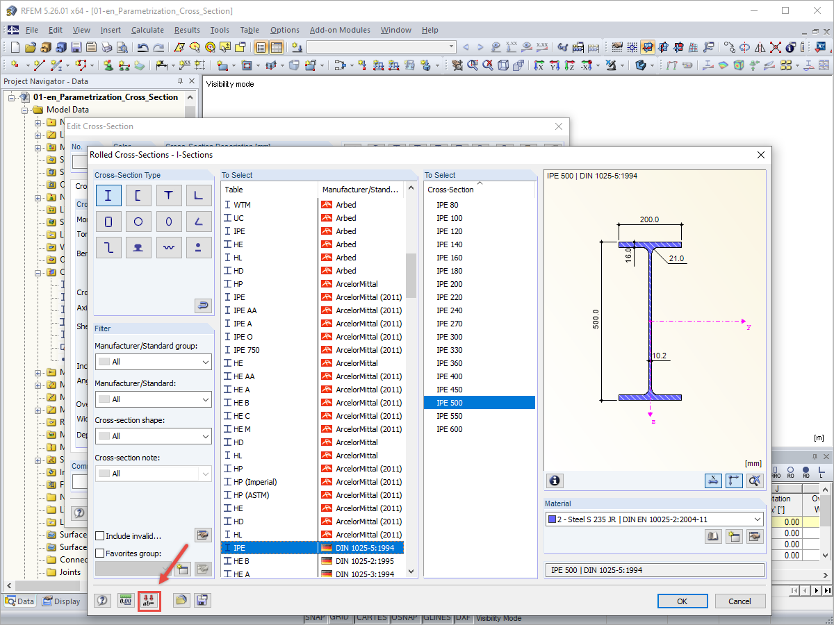
- Create a parametric section with the geometry based on the desired beam.
- Generate surfaces from members.
With this set of surfaces, it is recommended to copy the sine spline into the position of the top and bottom edge of the surface representing the web.
Later, it is required to change the geometry type of the web surface to Quadrangle and redefine the boundary lines of this element.
- Copy sine into the top and bottom of the web.
- Change the web geometry type to Quadrangle.
- Exclude straight lines from the web surface and add sine lines.
After preparing the geometry, it's required to focus on finishing the model for the calculation. Select the start and end lines of the member and create a member with the type Rigid.
After that, it's possible to define nodal supports on the beam and loads in the model. In order to check the resulting internal forces of a member, it is recommended to define a result beam on the main center line. Finishing all of these steps allows you to start the analysis of the beam.
- Define rigid members on the external lines of surfaces.
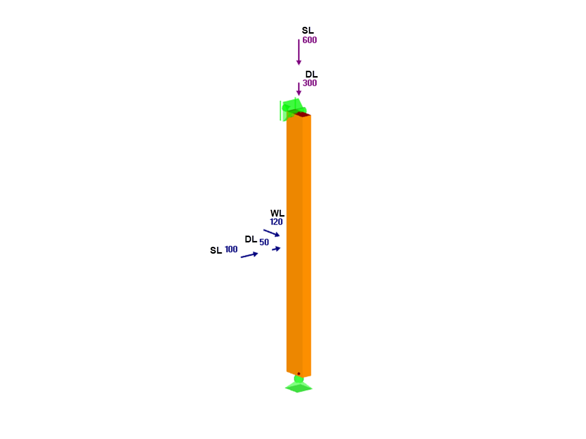
- Add nodal supports.
- Add loads – use line loads, not member loads for continuous loading.
- Define a result beam on the center line.
- Perform the analysis.
Remember to define proper mesh settings with an adequate target length of the finite elements and to use a line mesh refinement on the sine lines.


.png?mw=350&hash=c6c25b135ffd26af9cd48d77813d2ba5853f936c)






_1.jpg?mw=350&hash=ab2086621f4e50c8c8fb8f3c211a22bc246e0552)


.png?mw=600&hash=49b6a289915d28aa461360f7308b092631b1446e)


