Question
How can I control the stiffness reduction by load cases for surfaces?
Answer:
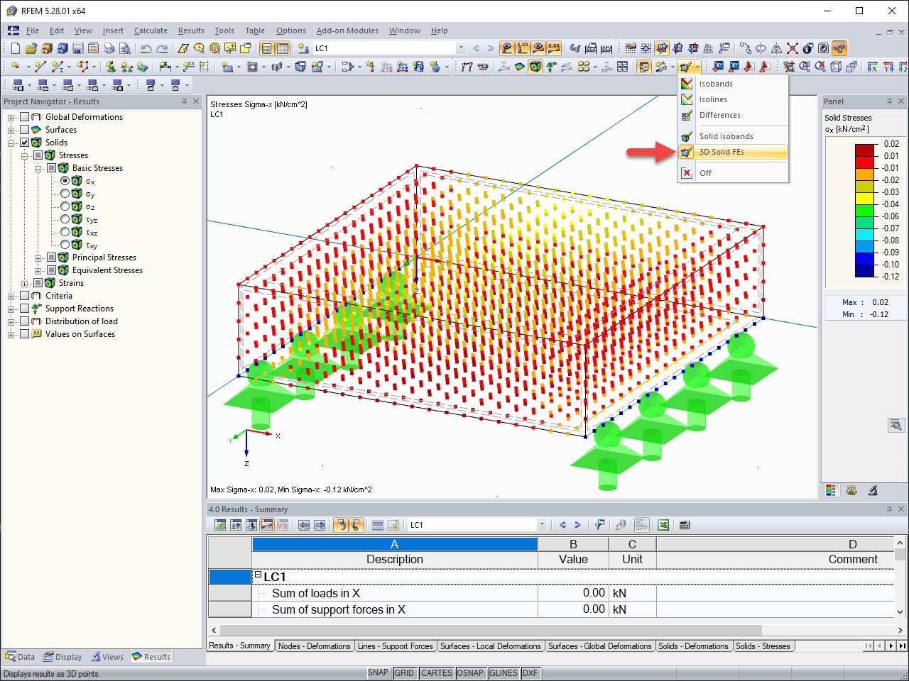
In the Edit dialog box of the respective surface, in the "Modify Stiffness" tab, you can select which type of stiffness modification is to be performed. For example, you can use "Multiplier Factors" as shown in Image 01.Multiplier factors can be specified for various stiffness components (for example, membrane stiffness).
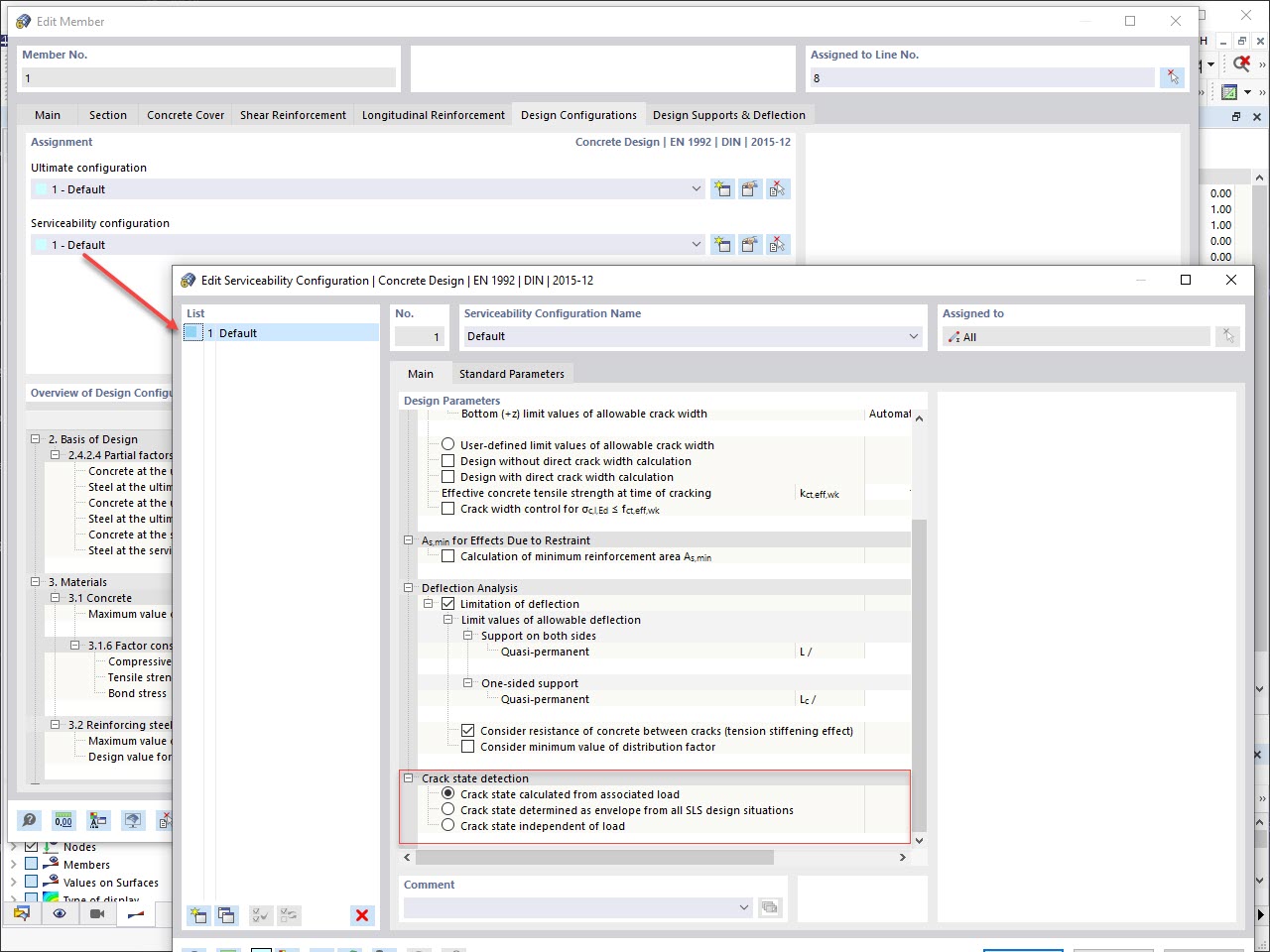
Whether these factors or the defined stiffness modification will be applied in the individual load cases or load combinations is controlled via the calculation parameters. Now, this means that the modification is taken into account as soon as the check box shown in Image 02 has been selected. When unselecting the check box, the modification will not be considered for the surfaces.
Thus, it is possible to control the stiffness modification by load case or load combination.
Author
Mr. Kieloch provides technical support to our customers and is responsible for development in the area of reinforced concrete structures.
Do you have any questions?
![Model](/en/webimage/011774/2600584/01-de.png?mw=512&hash=9f2525444a7414dfb1c05a73e375e9c4fe4f47b1)
Designing rigid end plate connections is difficult for four-row connection geometries and multi-axis bending stresses, because there are no official design methods.
![System with Local Axis System of Gusset Plate](/en/webimage/011743/3065040/01_-_en_us.jpg?mw=512&hash=2a77856259cebbe0dd4f7bd67111e0e92e909dd2)
The European standard EN 1993-1-8, Section 4.5.3.3. provides the user with a simplified method for the ultimate limit state design of fillet welds. According to the standard, the design is fulfilled if the design value of the resultant acting on the fillet weld area is smaller than the design value of the weld's load-bearing capacity. Thus, if you want to dimension the weld for a surface model, you will be faced with a variety of results due to the nature of FEM calculations. Therefore, we show in the following text how to determine the force components from the model.
![KB 001883 | Plate Girder Design According to AISC 360-22 in RFEM 6](/en/webimage/051561/3980997/im1.png?mw=512&hash=b8237709c4f30213fac51d86d32a42bddde72f03)
Plate girder is an economical choice for long spans construction. I-section steel plate girder typically has a deep web to maximize its shear capacity and flange separation, yet thin web to minimize the self-weight. Due to its large height-to-thickness (h/tw) ratio, transverse stiffeners may be required to stiffen the slender web.
![KB 001880 | Design of Cable Structures in RFEM 6 and RSTAB 9](/en/webimage/049985/3840051/Seil_QS_EN.png?mw=512&hash=83dd891c6124be9c686441c4b37fe92db2c2062d)
In this article, you will learn how to model and design cable structures in RFEM 6 or RSTAB 9.
![Feature 002423 | Displaying Results in Solids](/en/webimage/031923/3325382/FE_Solid_EN.jpg?mw=512&hash=d2950a5e2123942fab13aad296e814c67695c955)
The results of solid stresses can be displayed as colored 3D points in the finite elements.
![Feature 002842 | Sign-Dependent Stress Analysis](/en/webimage/051240/3953337/1.png?mw=512&hash=9d7f6c198b6d4ae6ee8f2fa8bca75f85579e14c9)
In the Stress-Strain Analysis add-on, you can use the option to specify sign-dependent limit stresses by stress component.
![Feature 002827 | Stresses Within Members](/en/webimage/050679/3922742/50679.png?mw=512&hash=89c2586ec7139690a213073aaa5a3e314c7ed023)
Get a better understanding of the stress distribution within member cross-sections by using clipping planes.
![Feature 002443 | Control of Crack Condition for Deformation and Crack Width Analysis](/en/webimage/032308/3333735/crackstate_EN.jpg?mw=512&hash=7a751769b3bfd152da28f9c235b662fe4a66d28f)
Various design parameters of the cross-sections can be adjusted in the serviceability limit state configuration. The applied cross-section condition for the deformation and crack width analysis can be controlled there.
For this, the following settings can be activated:
- Crack state calculated from associated load
- Crack state determined as an envelope from all SLS design situations
- Cracked state of cross-section - independent of load
Recommended Products for You