Removable guyed masts are used not only for telecommunications purposes, but also for collecting wind data in order to evaluate the profitability of a planned wind farm. Such removable and permanent towers can reach heights of up to 492 ft and are mounted at the planned windmill height in uninhabited areas.
CP 001163 | Guyed Mast for Wind Performance Measurements in Andalusia, Spain

The RF‑/STEEL EC3 add-on module automatically transfers the buckling line to be used for the flexural buckling analysis for a cross-section from the cross-section properties. The assignment of the buckling line can be adjusted manually in the module input for general cross-sections in particular, as well as for special cases.

This technical article deals with the design of structural components and cross-sections of a welded truss girder in the ultimate limit state. Furthermore, the deformation analysis in the serviceability limit state is described.

This technical article deals with the stability analysis of a roof purlin, which is connected without stiffeners by means of a bolt connection on the lower flange to have a minimum manufacturing effort.

This technical article analyzes the effects of the connection stiffness on the determination of internal forces, as well as the design of connections using the example of a two-story, double-spanned steel frame.

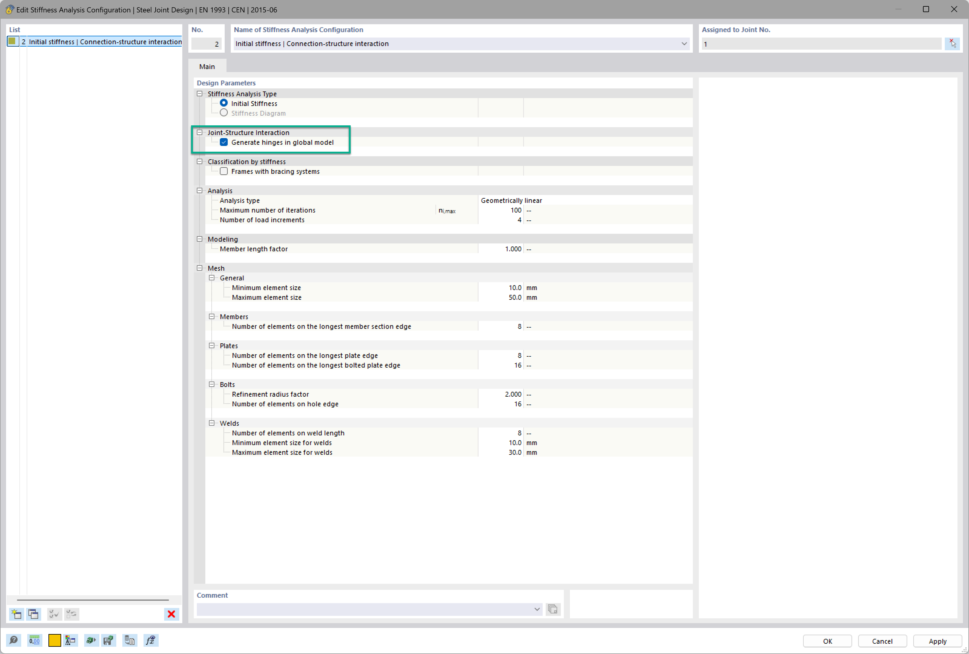
Want to automatically consider steel joint stiffness in your global RFEM model? Utilize the Steel Joints add-on!
Activate joint-structure interaction in the stiffness analysis of your steel joints. Hinges with springs are then automatically generated in the global model and included in subsequent calculations.

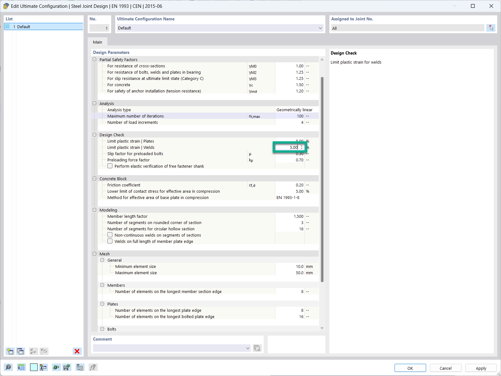
In the ultimate configuration of the steel joint design, you have the option to modify the limit plastic strain for welds.

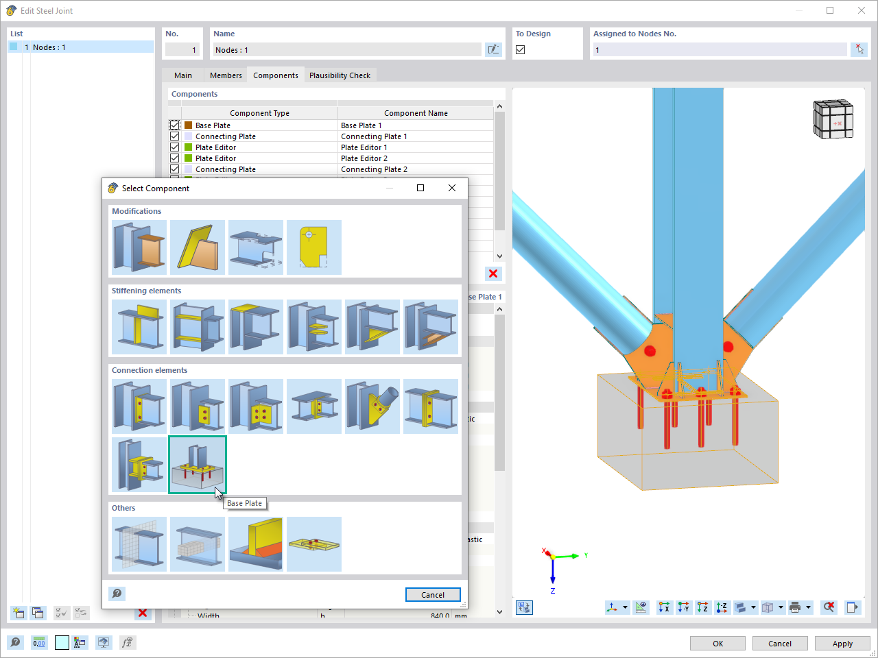
The "Base Plate" component allows you to design base plate connections with cast-in anchors. In this case, plates, welds, anchorages, and steel-concrete interaction are analyzed.

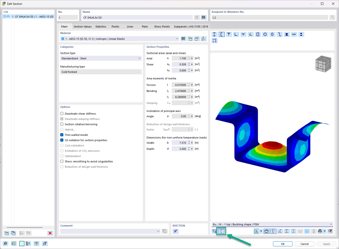
In the "Edit Section" dialog box, you can display the buckling shapes of the Finite Strip Method (FSM) as a 3D graphic.
I am designing a set of members using the equivalent member method in RF‑/STEEL EC3, but the calculation fails. The system is unstable, delivering the message "Non-designable - ER055) Zero value of the critical moment on the segment".
What could be the reason?
What could be the reason?
What is the meaning of the warning message ER061) Minimum amplifier of design loads?
In the RF‑/STEEL EC3 add-on module, I have selected two bracings with the same size as the shear panel type in the "Parameters" window for a beam to be designed. Thus, the beam should be supported laterally in the middle. Why is the eigenvector arbitrary, anyway?
Why are the equivalent member design checks grayed out in the Stability tab when activating the plastic design using the partial internal force method (RF‑/STEEL Plasticity)?
When calculating a cable using the STEEL EC3 add‑on module, there is the error message "Incorrect characteristic stresses for material No. 1! Please correct in Table 1.2."
I am designing an asymmetric cross-section and I got the message: "Non-designable: ER051 Moment about z-axis on asymmetric cross-section, taper, or set of members". Why?


_1.jpg?mw=350&hash=ab2086621f4e50c8c8fb8f3c211a22bc246e0552)


