A structure is made of four truss members, which are embedded into hinge supports. The structure is loaded by a concentrated force and alternatively by imposed nodal deformation over the critical limit point, when snap-through occurs. Imposed nodal deformation is used in RFEM 5 and RSTAB 8 to obtain the full equilibrium path of the snap-through. The self-weight is neglected in this example. Determine the relationship between the actual loading force and the deflection, considering large deformation analysis. Evaluate the load factor at given deflections.


Duration: 03:03:00 min

Duration: 00:00:06 min

Duration: 02:50:31 min

Duration: 01:34:46 min

Duration: 00:06:24 min

Duration: 04:21:12 min

Duration: 00:14:49 min

Duration: 00:02:42 min

Duration: 03:03:34 min


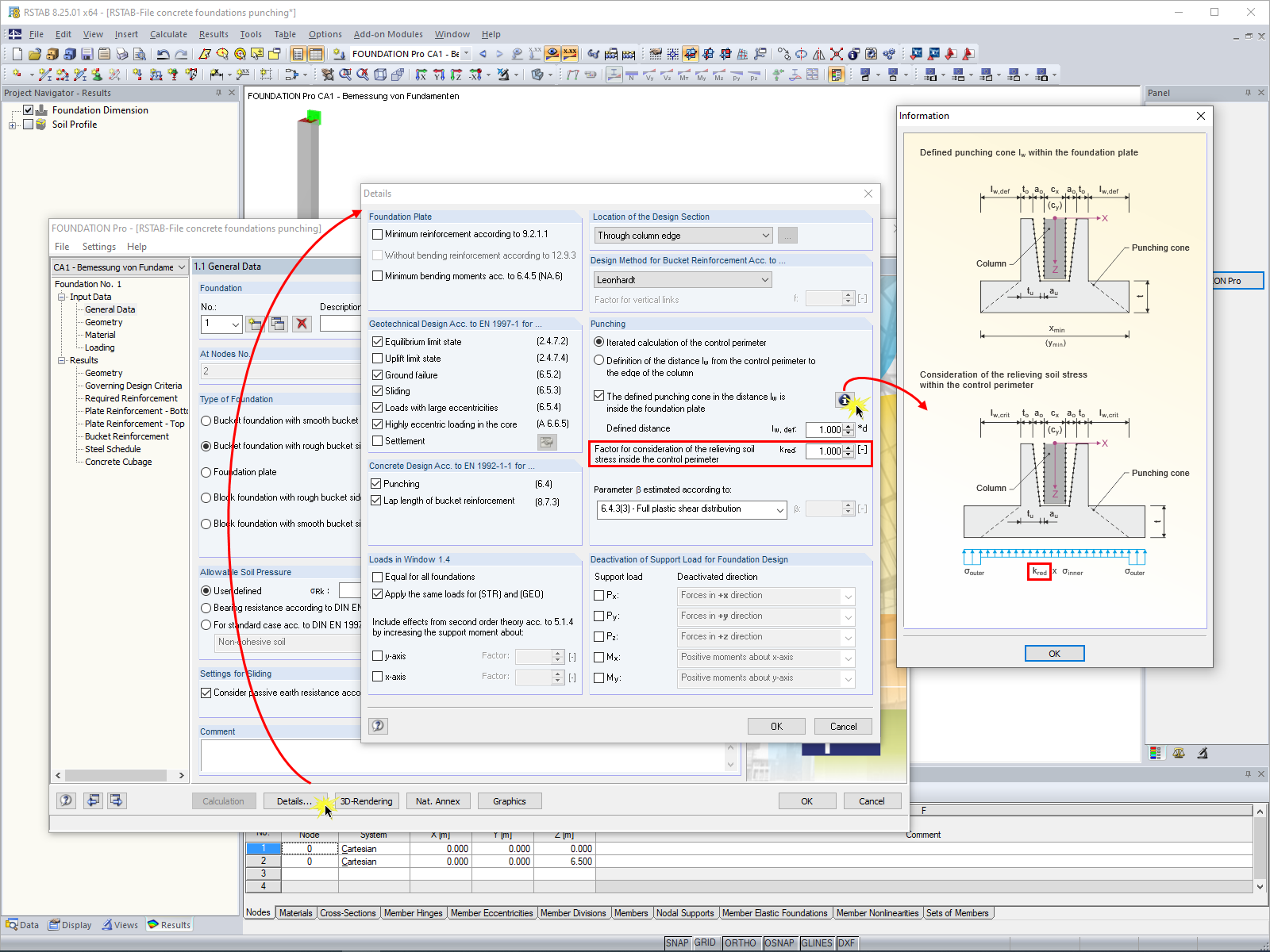
In RF-/FOUNDATION Pro, the user can freely select the proportion of the relieving soil pressure by means of the factor kred.
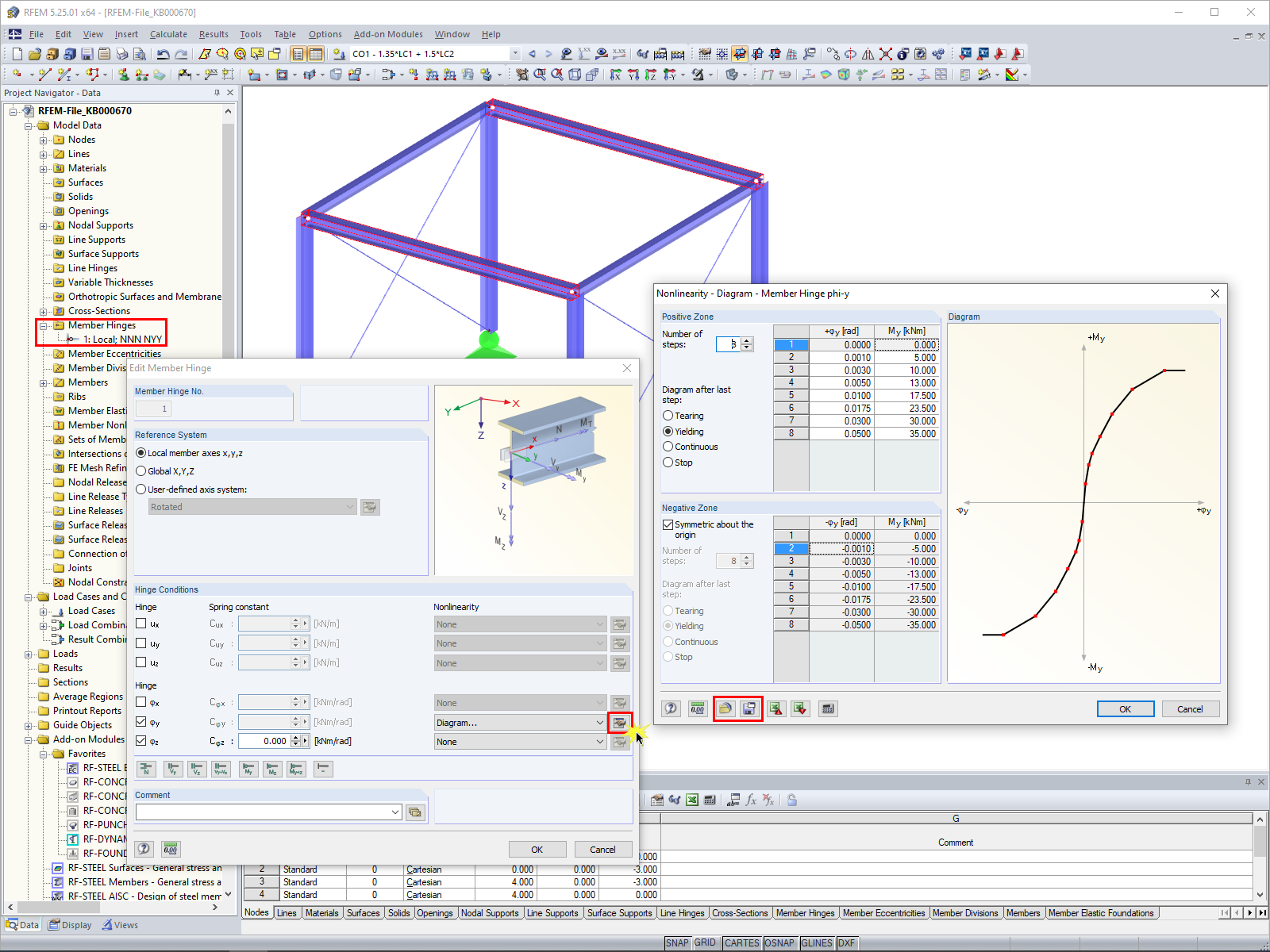
In RFEM 5 and RSTAB 8, it is possible to assign nonlinearities to member hinges. In addition to the nonlinearities "Fixed if" and "Partial activity", you can select "Diagram". If you select the "Diagram" option, you have to specify the according settings for the activity of the member hinge. For the individual definition points, it is necessary to specify the abscissa and ordinate values (deformations or rotations and the according internal forces) that define the hinge.

Utilizing the RF-STEEL AISC add-on module, steel member design is possible according to the AISC 360-16 standard. The following article will compare the results between calculating lateral torsional buckling according to Chapter F and Eigenvalue Analysis.
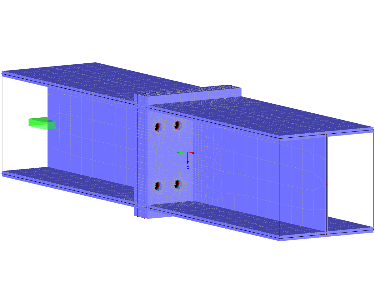
Designing rigid end plate connections is difficult for four-row connection geometries and multi-axis bending stresses, because there are no official design methods.


Want to automatically consider steel joint stiffness in your global RFEM model? Utilize the Steel Joints add-on!
Activate joint-structure interaction in the stiffness analysis of your steel joints. Hinges with springs are then automatically generated in the global model and included in subsequent calculations.

In the ultimate configuration of the steel joint design, you have the option to modify the limit plastic strain for welds.

The "Base Plate" component allows you to design base plate connections with cast-in anchors. In this case, plates, welds, anchorages, and steel-concrete interaction are analyzed.

In the "Edit Section" dialog box, you can display the buckling shapes of the Finite Strip Method (FSM) as a 3D graphic.
Are the models and presentations from Info Day 2018 freely available, and can you send them to me?
How do I display some results of all load cases in the printout report but other results of selected load cases only?
RF‑STEEL AISC add-module shows non-designable results for general cross-sections because of shear buckling checks according to Chapter G. How do I solve this?
Is it possible to model and design tapered castellated beams in RF-STEEL AISC?
Why are my steel members not being designed for stability in RF-STEEL AISC?
Is it possible to set user-defined values when viewing solid stress results?


_1.jpg?mw=350&hash=ab2086621f4e50c8c8fb8f3c211a22bc246e0552)

