2 Theoretical Background
- 2.1 Type of Model
- 2.2 Design of 1D and 2D Structural Components
-
2.6 Serviceability
- 2.6.1 Design Internal Forces
- 2.6.2 Principal Internal Forces
- 2.6.3 Provided Reinforcement
-
2.6.4 Serviceability Limit State Designs
- 2.6.4.1 Input data for the example
- 2.6.4.2 Check of principal internal forces
- 2.6.4.3 Required reinforcement for ULS
- 2.6.4.4 Specification of a reinforcement
- 2.6.4.5 Check of provided reinforcement for SLS
- 2.6.4.6 Selection of concrete compression strut
- 2.6.4.7 Limitation of Concrete Compressive Stress
- 2.6.4.8 Limitation of Reinforcing Steel Stress
- 2.6.4.9 Minimum Reinforcement for Crack Control
- 2.6.4.10 Check of rebar diameter
- 2.6.4.11 Design of bar spacing
- 2.6.4.12 Check of crack width
- 2.6.5 Governing Loading
-
2.7 Deformation Analysis with RF-CONCRETE Deflect
- 2.7.1 Material and Geometry Assumptions
- 2.7.2 Design Internal Forces
- 2.7.3 Critical Surface
- 2.7.4 Cross-Section Properties
- 2.7.6 Distribution Coefficient
- 2.7.7 Cross-Section Properties for Deformation Analysis
- 2.7.8 Material Stiffness Matrix D
- 2.7.9 Positive Definiteness of Material Stiffness Matrix
-
2.7.10 Example
- 2.7.10.1 Geometry
- 2.7.10.2 Materials
- 2.7.10.3 Selection of internal design forces
- 2.7.10.4 Determining the critical surface
- 2.7.10.5 Cross-section properties (cracked and uncracked state)
- 2.7.10.6 Shrinkage influence
- 2.7.10.7 Calculation of distribution coefficient
- 2.7.10.8 Final cross-section properties
- 2.7.10.9 Stiffness matrix of the material
5 Results
- 5.1 Required Reinforcement Total
- 5.2 Required Reinforcement by Surface
- 5.3 Required Reinforcement by Point
- 5.4 Serviceability Design Total
- 5.5 Serviceability Design by Surface
- 5.6 Serviceability Limit State Design by Point
- 5.7 Nonlinear calculation Total
- 5.8 Nonlinear Calculation by Surface
- 5.9 Nonlinear Calculation by Point
1 Introduction

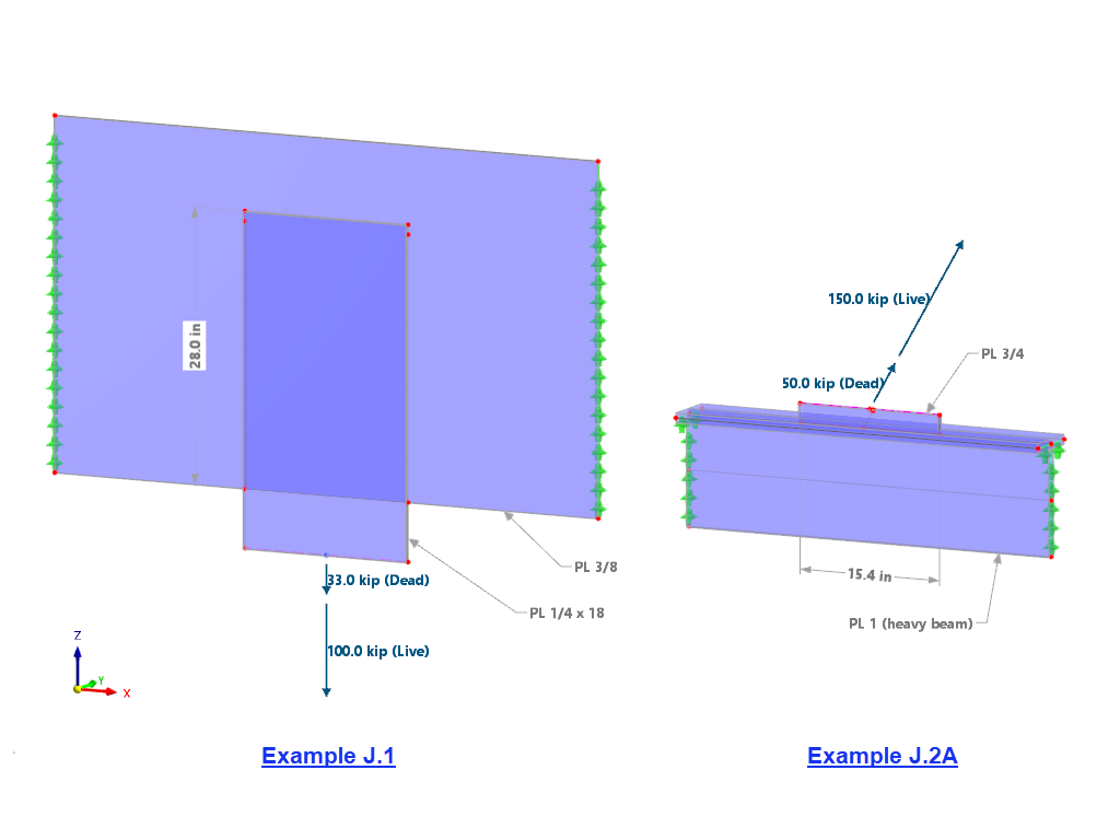
The weld stresses between surfaces can be determined using the Stress-Strain Analysis add-on in RFEM 6. Furthermore, the stress limit determined according to the applicable standard can be input to determine the stress ratio of the weld. This article focuses on the fillet weld design according to AISC 360-22 [1] with two examples from AISC Volume 1: Design Examples [2].

In the Stress-Strain Analysis add-on, you can use the option to specify sign-dependent limit stresses by stress component.

In the Stress-Strain Analysis add-on, you can define a component-dependent limit stress cycle and consider it in the design.

In RFEM 6, it is possible to define line welds between surfaces and to calculate the weld stresses by using the Stress-Strain Analysis add-on.
The following joint types are available:
- Butt Joint
- Corner Joint
- Lap Joint
- Tee Joint
Depending on the selected joint type, you can select the following weld types:
- Single Square
- Double Square
- Double Bevel
- Single V
- Double V
- Single U
- Double U
- Single J
- Double J

Compared to the RF‑/STEEL add-on module (RFEM 5 / RSTAB 8), the following new features have been added to the Stress-Strain Analysis add-on for RFEM 6 / RSTAB 9:
- Treatment of members, surfaces, solids, welds (line welded joints between two and three surfaces with subsequent stress design)
- Output of stresses, stress ratios, stress ranges, and strains
- Limit stress depending on the assigned material or a user-defined input
- Individual specification of the results to be calculated through freely assignable setting types
- Non-modal result details with prepared formula display and additional result display on the cross-section level of members
- Output of the design check formulas used
How can I change the display size of formulas in the result details?
Why are the stresses of the structural analysis different from those calculated with the Stress-Strain Analysis add-on?
The limit stress is activated, but my stress ratio is “non-designable” in the Stress-Strain Analysis add-on. What could be the reason?
Is it possible to display the deformation analysis of a surface (limit 0.5‰)?
Where can I find the materials for the corresponding National Annexes in RFEM 6 and RSTAB 9?
.png?mw=350&hash=c6c25b135ffd26af9cd48d77813d2ba5853f936c)


