Two-Directional Reinforcement Meshes with k > 0
For a reinforcement with two reinforcement directions subjected to two positive principal axial forces N1 und N2, choose the direction of the concrete compressive strut as follows.
There are basically two ways to arrange a compression strut exactly at the center between two crossing reinforcement directions.
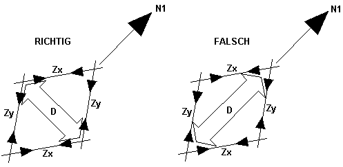
In the figure on the left, the stiffening concrete compression strut divides the obtuse angle between the crossing reinforcement directions; in the figure on the right, it divides the acute angle. The strut on the left stiffens the reinforcement mesh in the desired way, whereas the concrete compression strut shown in the figure on the right allows the reinforcement mesh to be arbitrarily deformed by the force N1.
Um sicherzustellen, dass die Druckstrebe den korrekten Winkel teilt, werden die Bemessungskräfte Zx, Zy und Zz mithilfe Gleichung 2.5, Gleichung 2.6 und Gleichung 2.7 für beide geometrisch möglichen Richtungen der Druckstrebe ermittelt. A wrong direction of the compression strut would result in a tensile force.
Therefore, the following directions of the concrete compression strut are analyzed:
and
To distinguish the analyzed directions, the index "1a" is assigned to the simple arithmetic mean value and the index "1b" is assigned to the direction of the compression strut that is rotated by 90°.
The following graph shows that for the equilibrium of forces, a tension force is respectively obtained in the two reinforcement directions and a compression force in the selected direction of the compression strut.
Die Untersuchungen von Baumann setzen bestimmte Wertebereiche für die verschiedenen Winkel voraus. The angle α (between the principal axial force N1 and the reinforcement direction closest to it) thus has to be between 0 and π/4. The angle β must be greater than α + π/2.
In [1] wird die Tabelle IV mit den möglichen Gleichgewichtszuständen vorgestellt (siehe Bild 2.15). Rows 1 through 4 of this table show the possible states of equilibrium for walls that are only subjected to tension. Row 4 shows the state of equilibrium with two directions of reinforcement subjected to tension and a compression strut. Rows 5 to 7 show walls for which the principal axial forces have different algebraic signs.
The second column of this table defines the value range of the loading.
The third column indicates the number of reinforcement directions subjected to a tension force for this state of equilibrium.
Die vierte Spalte (β) zeigt den Wertebereich der Bewehrungsrichtung β auf. In RF-CONCRETE Surfaces, this range is not available as it results from the directions of reinforcement specified in the input data.
Die fünfte Spalte (γ) gibt die Richtung der inneren Kraft Zz aus. In most cases, this is the direction of the compression strut computed by the program; however, it can also be a user-defined third reinforcement direction to which a tension force is actually assigned.
Ob die Kraft in die Richtung γ tatsächlich eine Druckkraft ist, ist der siebten Spalte zu entnehmen.
The penultimate column shows the required internal forces together with their directions. Reinforcement directions with a tension force are represented by simple lines whereas possible compression struts are indicated by dashed lines.
Literature
[1] Deutscher Ausschuss für Stahlbeton, Heft 217: Tragwirkung orthogonaler Bewehrungsnetze beliebiger Richtung in Flächentragwerken aus Stahlbeton (von Theodor Baumann). Verlag Ernst & Sohn, Berlin, 1972.


