Limitation of reinforcing steel stress
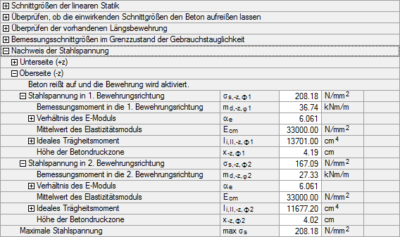
In window 1.3 Surfaces, the tension stresses of the reinforcing steel reinforcement are limited to σs,max = 0.8 ⋅ fyk according to EN 1992-1-1, clause 7.2(5) (see Figure 2.90).
For BSt 500 S (B), the maximum steel stress σs,max is thus determined as:
The maximum stress σs,max is to be compared with the provided tension stress for both reinforcement directions.
The provided tension stress σs is determined as follows:
|
αE |
Relation of the elastic modulus (Es/Ecm) |
|
mEd |
Applied moment |
|
d |
Effective depth |
|
x |
Depth of concrete compression zone |
|
Ii, II |
Ideal moment of inertia in state II |
|
b |
Width of element (always 1m for plates) |
|
as |
Provided tension reinforcement |
|
b |
Width of element (always 1m for plates) |
|
αe |
Effective modular ratio |
|
as |
Provided tension reinforcement |
|
d |
Effective depth |
Mit den in Kapitel 2.6.4.6 ermittelten Werten lassen sich die vorhandenen Zugspannungen σs,u,φ1 und σs,u,φ2 in die beiden Bewehrungsrichtungen φ1 und φ2 wie folgt bestimmen:
Die vorhandenen Zugspannungen σs,-z,φ1 und σs,-z,φ2 sind somit kleiner als die maximale Stahlspannung σs,max (siehe Bild 2.90).
Der maßgebende Quotient von vorhandener zu zulässiger Stahlspannung liegt in die Bewehrungsrichtung φ1 vor. The design is fulfilled.

