Minimum reinforcement for crack control
The minimum reinforcement area for crack control is determined according to EN 1992-1-1, clause 7.3.2, Equation (7.1).
|
kc |
Coefficient for considering the influence of the stress distribution in the cross-section prior to cracking as well as the change of the internal lever arm |
|
k |
Coefficient for considering non-uniform self-equilibrating stresses, which lead to the reduction of restraint forces |
|
fct,eff |
Mean value of the effective tensile strength of the concrete, to be expected when the cracks occur |
|
Act |
Area of the concrete tension zone (part of the cross-section or partial cross-section that is calculated to be in tension in the uncracked state under the action combination that leads to the formation of the first crack at the gross cross-section) |
|
σs |
Absolute value of the maximum allowable stress in the reinforcement immediately after crack formation |
The maximum bar diameter d*s is determined according to EN 1992-1-1, clause 7.3.3 (2) depending on the actually provided diameter ds from the rearranged Equation (7.6N).
|
ds |
Adjusted maximum bar diameter |
|
d*s |
Maximum bar diameter according to EN 1992-1-1, Table 7.2 (see Figure 2.96) |
|
h |
Overall depth of cross-section |
|
hcr |
Depth of tensile zone immediately prior to cracking while taking the characteristic values of prestress and axial forces under the quasi-permanent action combination into account |
|
d |
Effective depth up to the centroid of outside reinforcement |
In our example, determining the minimum reinforcement at the plate's bottom surface is excluded by opening the following dialog box in the Limit of Crack Width tab of window 1.3 Surfaces. In it, the check boxes for the Bottom (+z) reinforcement have to be cleared.
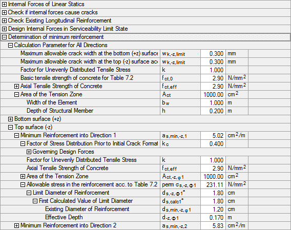
The limit diameter d*s,-z,φ1 for the reinforcement direction φ1 at the top side of the plate is determined according to Equation 2.72.
Analog ergibt sich für die Bewehrungsrichtung φ2 der Grenzdurchmesser d*s,-z,φ2:
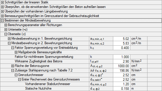
In Maske 1.3 Flächen ist die zulässige Rissbreite wk,max von 0.3 mm vorgegeben (siehe Bild 2.97). Mit den Grenzdurchmessern d*s,-z,φ1 = 18.00 mm und d*s,-z,φ2 = 25.20 mm kann aus EN 1992-1-1, Tabelle 7.2N (siehe Bild 2.96) die zulässige Spannung σs interpoliert werden.
These allowable steel stresses are also shown in Figure 2.98 and Figure 2.99.
Die Stahlspannung in Richtung φ2 ist maßgebend.
The area of the concrete tension zone in the cross-section is determined as follows:
Somit ergibt sich gemäß Gleichung 2.71 für die 2. Bewehrungsrichtung folgende Mindestbewehrung:
For this reinforcement direction, the applied reinforcement is greater than the minimum reinforcement. The following check criterion is thus obtained:


