Stiffening effect of concrete in tension area
In cracked parts of the reinforced concrete, the tensile forces in the crack are resisted by the reinforcement alone. Between two cracks, however, tension stresses are transferred to the concrete through the (displaceable) bond. Thus, the concrete contributes to the resistance of the internal tensile forces, which leads to an increased stiffness of the structural component. This effect refers to the stiffening contribution of the concrete in tension between the cracks and is also called tension stiffening.
The increase of the structural component stiffness due to tension stiffening can be considered in two ways:
- A residual, constant tension stress, which remains after the crack formation, can be involved in the concrete's stress-strain diagram.
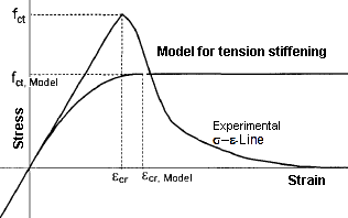
The residual tension stress is clearly smaller than the tensile strength of the concrete.As an alternative, it is also possible to introduce modified stress-strain relations for the tension zone, which consider the contribution of the concrete in tension between the cracks in the form of a decreasing branch in the graph after the tensile strength is reached.
- Another approach is to modify the "pure" stress-strain diagram of the reinforcing steel.
In this case, a reduced steel strain εsm is applied in the relevant cross-section, with the strain resulting from εs2 and a reduction term due to the tension stiffening.
RF-BETON NL verwendet für die Berücksichtigung von Tension Stiffening den Ansatz über die Modellierung der Betonzugfestigkeit nach Quast [4]. This model is based on a defined stress-strain relation of the concrete in the tension area (parabola-rectangle diagram). The basic assumptions of Quast's approach can be summarized as follows:
- full contribution of the concrete to tension until reaching the crack strain εcr or the calculational concrete tensile strength fct,R
- Reduzierte versteifende Mitwirkung des Betons in der Zugzone entsprechend der vorhandenen Betondehnung.
- Kein Ansatz von Tension Stiffening nach dem Einsetzen des Fließens des maßgebenden Bewehrungsstabes.
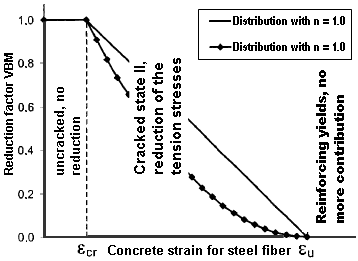
Zusammenfassend bedeutet dies, dass die rechnerische Zugfestigkeit fct,R keine fixe Größe ist, sondern sich auf die vorhandene Dehnung in der maßgebenden Stahl(zug)faser bezieht. Die maximale Zugfestigkeit fct,R nimmt ab der definierten Rissdehnung εcr bis zum Erreichen der Fließdehnung des Bewehrungsstahls in der maßgebenden Stahlfaser linear auf null ab.Erreicht wird dies durch die in Bild 2.137 gezeigte Spannungs-Dehnungs-Linie im Zugbereich des Betons (Parabel-Rechteck-Diagramm) und die Ermittlung eines Reduktionsfaktors VMB ( Versteifende Mitwirkung des Betons).
The stress-strain relation in the tension zone can be described with the following equations:
für 0 < ε < εcrσc = VMB · fct,R
To determine the reduction factor VMB, the strain at the most tensioned steel fiber is used. The position of the reference point is shown in Figure 2.139.
Der Abminderungsfaktor VMB nimmt mit steigender Stahldehnung ab.Im Diagramm für den Faktor VMB (siehe Bild 2.140) ist ersichtlich, dass der Faktor VMB genau zum Fließbeginn der Bewehrung auf null reduziert wird.
The distribution for the reduction factor VMB in state II (ε > εcr) can be controlled by means of the exponent nVMB. Erfahrungswerte sind nach Pfeiffer [5] die Werte nVMB = 1 (linear) bis nVMB = 2 (Parabel) für biegebeanspruchte Bauteile. Quast [6] benutzt in seinem Modell den Exponenten nVMB = 1 (linear) und erzielt damit gute Übereinstimmungen bei der Nachrechnung von Stützenversuchen. Nach Pfeiffer [5] lassen sich mit nVMB = 2 reine Zugversuche mit akzeptabler Übereinstimmung abbilden.
The assumption of a parabola-rectangle diagram for the cracked concrete tension zone can be regarded as a calculation aid. At first glance, there are great differences compared to the experimentally determined stress-strain diagrams on the tension side of the pure concrete.
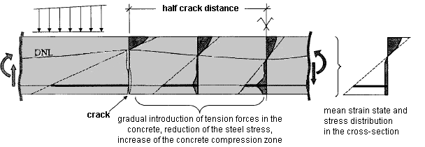
The given stresses in the reinforced concrete cross-section in bending show that the parabola-rectangle diagram is indeed better suited to describe the mean of the strains and stresses.
In a bending beam, a concrete body forms between two cracks. It acts as a sort of wall into which tension forces are gradually reintroduced by the reinforcement. This results in a very irregular distribution of stress and strain. On average, however, we can create a plane of strain with a parabola-rectangle distribution with which it is possible to consider the mean curvature.
Quast suggests the following calculation value for the tension strength fct,R and the crack strain εcr,R for his model.
The calculational value for the tensile strength fct,R is thus smaller than specified by the Eurocode. This is due to the description of the stress-strain relation and the determination of the reduction parameter VMB, in which the assumed tension stress and the resulting tension force are only slowly reduced after exceeding the tension strain. For a strain of 2 ⋅ εcr, there is also an acting tension stress of about 0.95 ⋅ fct,R. Thus, in case of bending, the reduction of the stiffness can be predicted well. Bei einer reinen Zugbeanspruchung sind die o. g.Werte für fct,R zu gering. Hier sollten nach Pfeiffer [5] die Werte aus EC 2 für den Rechenwert der Zugfestigkeit angesetzt werden.
Die von Quast [6] empfohlenen Werte für fct,R = 1/20 ⋅ fcm sind durch den Ansatz von 60 % der in EC 2 angegebenen Zugfestigkeiten zu erreichen. Bei dem Ansatz von fct,R = 0.6 ⋅ fctm wird einerseits das Aufreißen des Querschnittes zu früh vorhergesagt.Andererseits ist aber dadurch eine Reduktion der Zugfestigkeit unter Dauerlast (ca. 70 %) oder eine temporär höhere Last (z. B. das kurzzeitige Aufbringen der seltenen Einwirkungskombination), die zu einer geschädigten Zugzone führt, bereits berücksichtigt.
The individual calculation values for the concrete's tension zone can be described as follows:
Exponent für allgemeine Parabel (siehe Gleichung 2.93):
Literature
[4] Quast, Ulrich. Zur Mitwirkung des Betons in der Zugzone. Beton und Stahlbetonbau, Heft 10, 1981.
[5] Pfeiffer, Uwe. Die nichtlineare Berechnung ebener Rahmen aus Stahl- oder Spannbeton mit Berücksichtigung der durch das Aufreißen bedingten Achsendehnung. Cuviller Verlag, Göttingen, 2004.
[6] Quast, Ulrich. Zum nichtlinearen Berechnen im Stahlbeton- und Spannbetonbau. Beton und Stahlbetonbau, Heft 9 und Heft 10, 1994.


