- General stress analysis
- Automatic import of internal forces from RFEM/RSTAB
- Graphical and numerical output of stresses, strains, clearance, and design ratios fully integrated in RFEM/RSTAB
- User-defined specification of the limit stress
- Summary of similar structural components for the design
- Wide range of customization options for graphical output
- Clearly arranged result tables for a quick overview after the design
- Simple traceability of the results due to the complete documentation of the calculation method, including all formulas
- High productivity due to the minimal amount of input data required
- Flexibility due to detailed setting options for basis and extent of calculations
- Gray zone display for unimportant value ranges: Product Feature "Stress-Strain Analysis with Gray Zone Display"
Stress-Strain Analysis | Features


Duration: 00:00:12 min

Duration: 00:00:21 min

Duration: 00:12:36 min

Duration: 00:02:14 min

Duration: 00:01:03 min

Duration: 00:00:40 min

Duration: 00:01:06 min

Duration: 00:00:26 min

Duration: 00:01:01 min


Cable and tensile membrane structures are regarded as very slender and aesthetic building structures. The partly very complex double-curved shapes can be found using suitable form-finding algorithms. One possible solution is to search for the form via the equilibrium between the surface stress (provided prestress and an additional load such as self-weight, pressure, and so on) and the given boundary conditions.
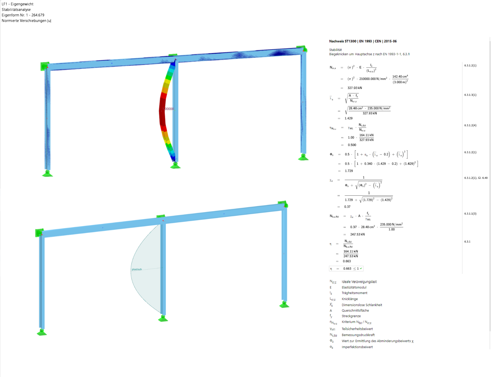
Every day, thousands of structural engineers design structural components using design check formulas that include the critical buckling load. But where do these old formulas come from, that Leonard Euler established over 200 years ago and that form the basis of all three structural steel design concepts?
![Basic Shapes of Membrane Structures [1]](/en/webimage/009595/2419502/01-en-png-png.png?mw=512&hash=6ca63b32e8ca5da057de21c4f204d41103e6fe20)
This paper is focused on the specific aspects of designing membrane structures that have specific requirements, such as form-finding and cutting pattern generation. An integral part of the design of these structures is the process of finding suitable prestressed shapes and generating cutting patterns. The text briefly describes two basic processes in the design of membrane structures. The physical principles are explained and the individual theses illustrated by examples.
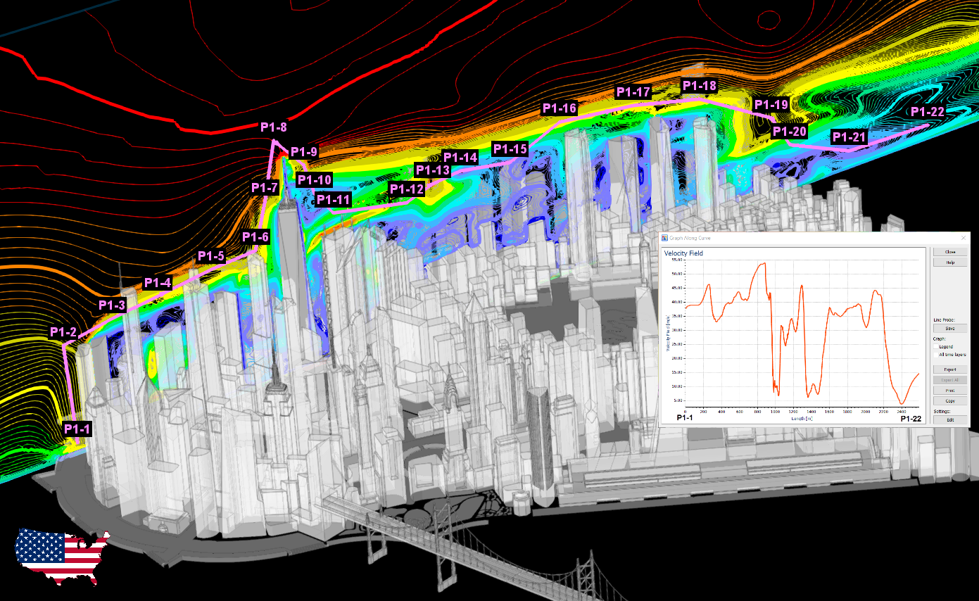
Compliance with building codes, such as Eurocode, is essential to ensure the safety, structural integrity, and sustainability of buildings and structures. Computational Fluid Dynamics (CFD) plays a vital role in this process by simulating fluid behavior, optimizing designs, and helping architects and engineers meet Eurocode requirements related to wind load analysis, natural ventilation, fire safety, and energy efficiency. By integrating CFD into the design process, professionals can create safer, more efficient, and compliant buildings that meet the highest standards of construction and design in Europe.


The nonlinear calculation adopts the real mesh geometry of planar, buckled, simple curved, or double curved surface components from the selected cutting pattern and flattens this surface component in compliance with the minimization of distortion energy, assuming defined material behavior.
In simplified terms, this method attempts to compress the mesh geometry in a press, assuming frictionless contact, and to find the state in which the stresses from flattening in the component are in equilibrium in the plane. This way, minimum energy and optimum accuracy of the cutting pattern are achieved. Compensation for warp and weft as well as compensation for boundary lines are considered. Then, the defined allowances on boundary lines are applied to the resulting planar surface geometry.
Features:
- Minimization of distortion energy in the flattening process for very accurate cutting patterns
- Application for almost all mesh arrangements
- Recognition of adjacent cutting pattern definitions to keep the same length
- Mesh application for main calculation

- Planar and geodesic cutting lines
- Flattening of double-curved surface parts of tensioned membranes or pneumatic cushions
- Definition of cutting patterns by using boundary lines which are not required to be connected
- Sophisticated flattening based on the minimum energy theory
- Welding and boundary allowances
- Uniform or linear compensation in warp and weft direction
- Possibility of different compensations for boundary lines
- Adaptable data organisation (any additional modification of input data is considered up to the final "weld")
- Graphical display of cutting patterns
- Statistical information about each cutting pattern (width, length, size)
- Option to automatically generate cutting patterns from cells

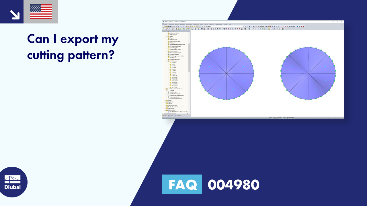
After the calculation, the "Point Coordinates" tab appears in the cutting pattern dialog box. In this tab, the result is displayed in the form of a table with coordinates and a surface in the graphical window. The coordinate table presents new flattened coordinates relative to the centroid of the cutting pattern for each mesh node. Furthermore, the cutting pattern with the coordinate system at the centroid is represented in the graphical window. When selecting a table cell, the respective node is displayed with an arrow in the graphic. In addition, the area of the cutting pattern is displayed below the node table.
Moreover, standard stress/strain results for each pattern are displayed in the RF‑CUTTING‑PATTERN load case in RFEM.
Features:
- Results in a table, including information about the cutting pattern
- Smart table relating to the graphic
- Results of flattened geometry in a DXF file
- Output of strains after flattening in order to evaluate the cutting patterns
- Results of strains after flattening for the evaluation of patterns
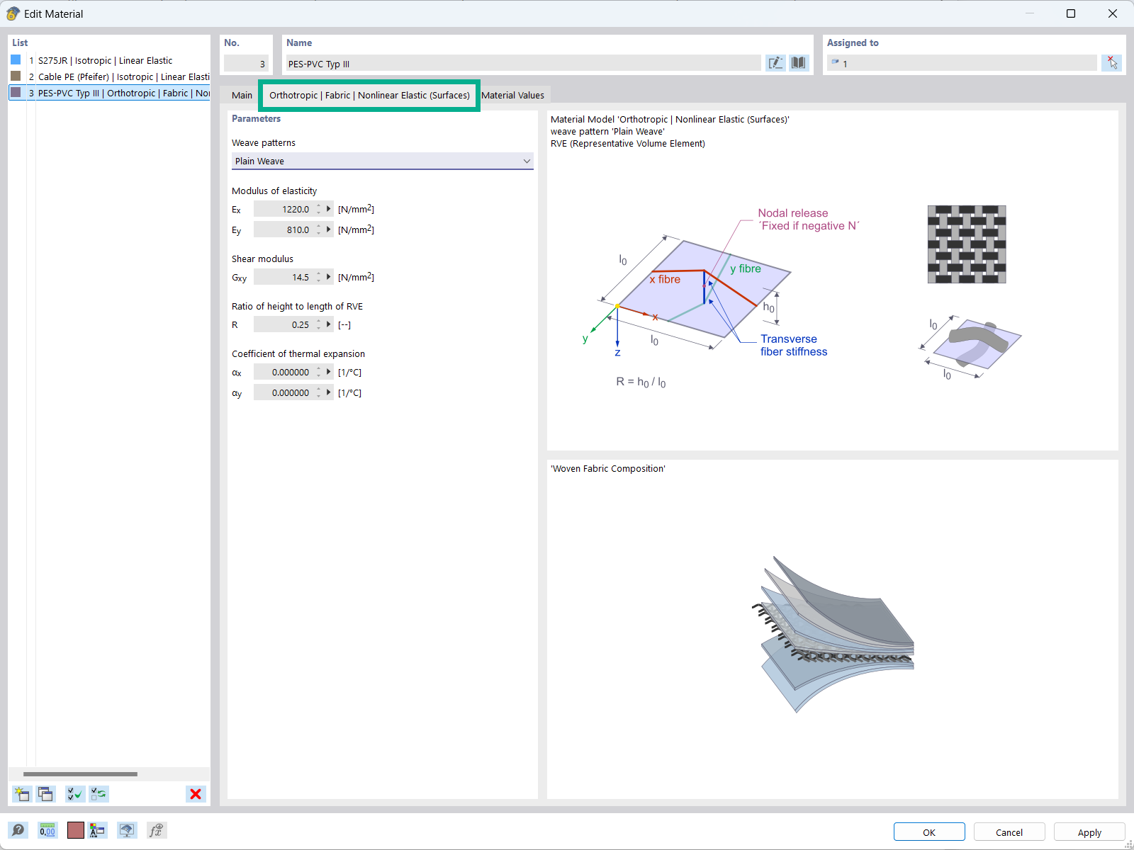
The "Orthotropic | Fabric | Nonlinear Elastic (Surfaces)" material model allows you to define prestressed fabric membranes using the representative microstructure-solid element model – RVE.
By considering the fabric geometry in the microstructure model, the corresponding transversal strain effect can now be considered for all force conditions in the membrane.
Can I export my cutting pattern?
How can I define a material allowance at the edge of a cutting pattern?
How is it possible to create the cutting pattern geometry for a decorative sticker on a biaxially curved membrane roof?
How are the properties of the elasticity and shear modulus of a membrane fabric with the usual force/length syntax transformed into the general force/surface syntax to be entered in RFEM?
Why does the direction of a cutting pattern edge line in the support area change abruptly?
How can I recognize that the RF‑CUTTING‑PATTERN flattening process has found the convergence?


Recommended Products for You
RFEM 6 | Main Program RFEM 6

The new generation of 3D FEA software is used for the structural analysis of members, surfaces, and solids.
Price of First License
4,790.00 USD
RFEM 6 | Additional Analysis

The Form-Finding add-on finds the optimal shape of members subjected to axial forces and tension-loaded surface models. The shape is determined by the equilibrium between the member axial force or the membrane stress and the existing boundary conditions.
Price of First License
2,320.00 USD
RFEM 5 | Main Program RFEM

Structural engineering software for a finite element analysis (FEA) of planar and spatial structural systems consisting of plates, walls, shells, members (beams), solids, and contact elements
Price of First License
4,690.00 USD
RFEM 5 | Tensile Membrane Structures

Form-finding of tensile membrane and cable structures
Price of First License
2,320.00 USD
RFEM 5 | Tensile Membrane Structures

Generation of cutting patterns for tensile membrane structures
Price of First License
2,820.00 USD
RFEM 6 | Design

The Steel Design add-on performs the ultimate and serviceability limit state design checks of steel members according to various standards.
Price of First License
2,970.00 USD