Irregularities in the cross-section geometry can be displayed as point elements. They can be added as rounding, rectangle, circle, or triangle, or removed from member surfaces. This way, you can additionally consider or exclude the area of the point element for the cross-section properties.
You can insert the point elements using the menu "Insert" → "Cross-Section Data" → "1.5 Point Elements", or the corresponding button in the toolbar (Image 01).
No stresses are displayed on the point elements. The point elements are not included in the calculation of the torsional constant. This can be compensated by a correction factor in the Calculation Parameters dialog box (Image 02) in order to determine distinct rounding, for example.
Furthermore, you can use the "Create Round or Angled Corner" function to provide corners and edges of the cross-section with a fillet radius and bending. This function is available in the menu Edit → Create Round or Angled Corner menu (Image 03). In the Corner Type dialog section, specify if the corner zone should be made round or angled. Depending on the selection, you have to enter the fillet radius r or a reduction by the lengths l1 and l2 in the Parameters dialog section.
Both elements can be selected by clicking in the work window without closing the dialog box. The line numbers are shown in the "Create Between Lines Nos." section.
If the "Cut lines" check box is selected, RFEM deletes the extensions of the original elements that overlap in the corner zone after creating the arc or the new element. The Delete corner option also removes the node in the corner.
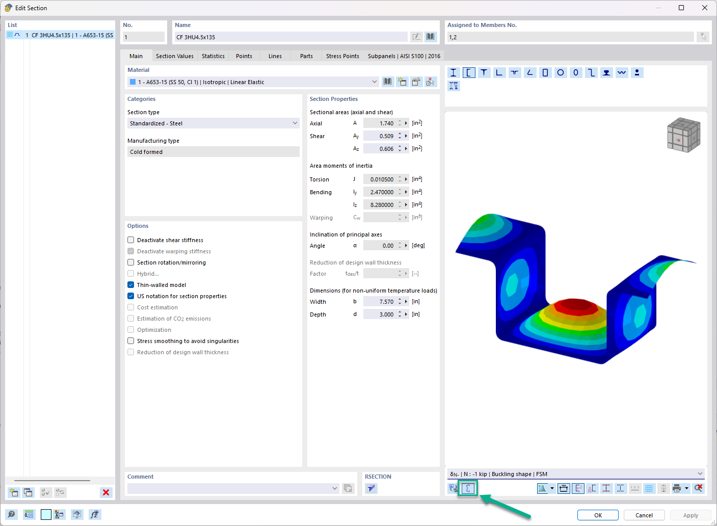
Furthermore, you can use the "Smooth Corner" function to model detailed corner areas without using the rectangular point elements (Image 04). This function is available in the menu Edit → Smooth Corner. Then, click one of the two elements in the intersection area in the work window. The respective element side is shortened; the adjacent element side is extended accordingly. A null element creates the connection between the elements.


,_LC1__LI.jpg?mw=350&hash=d5094e5e08f06adf09ec37d550e00fd357782bec)
,_LC1__LI.jpg?mw=350&hash=6ed041c2883863d5ca78996c15f07c7d24cb0baf)
,_LC1__LI.jpg?mw=350&hash=6ed041c2883863d5ca78996c15f07c7d24cb0baf)
,_LC1__LI.jpg?mw=350&hash=6ed041c2883863d5ca78996c15f07c7d24cb0baf)
,_LC1_LI.jpg?mw=350&hash=871f19dacc172cbb19cbdefc7c490c9db999ca2b)


_1.jpg?mw=350&hash=ab2086621f4e50c8c8fb8f3c211a22bc246e0552)


